
3Com Switch 8800 Advanced Software V5 Configuration Guide


19
IP ROUTING OVERVIEW
Go to these sections for information you are interested in:
■ “IP Routing and Routing Table” on page 187
■ “Routing Protocol Overview” on page 189
■ “Displaying and Maintaining a Routing Table” on page 191
n
The term "router" or router icon in this document refers to a router in a generic
sense or a Layer 3 switch.
IP Routing and
Routing Table
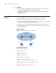
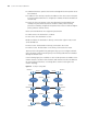
Routing Routing in the Internet is achieved through routers. Upon receiving a packet, a
router finds an optimal route based on the destination address and forwards the
packet to the next router in the path until the packet reaches the last router, which
forwards the packet to the intended destination host.
Routing Through a
Routing Table
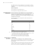
Routing table
Routing tables play a key role in routing. Each router maintains a routing table,
and each entry in the table specifies which physical interface a packet destined for
a certain destination should go out to reach the next hop (the next router) or the
directly connected destination.
Routes in a routing table can be divided into three categories by origin:
■ Direct routes: Routes discovered by data link protocols, also known as interface
routes.
■ Static routes: Routes that are manually configured.
■ Dynamic routes: Routes that are discovered dynamically by routing protocols.
Contents of a routing table
A routing table includes the following key items:
■ Destination address: Destination IP address or destination network.
■ Network mask: Specifies, in company with the destination address, the address
of the destination network. A logical AND operation between the destination
address and the network mask yields the address of the destination network.
For example, if the destination address is 129.102.8.10 and the mask
255.255.0.0, the address of the destination network is 129.102.0.0. A
network mask is made of a certain number of consecutive 1s. It can be
expressed in dotted decimal format or by the number of the 1s.