
3Com Switch 8800 Advanced Software V5 Configuration Guide


202 CHAPTER 21: PROXY ARP CONFIGURATION
Displaying and
Maintaining Proxy
ARP
Proxy ARP
Configuration
Example
Network requirement
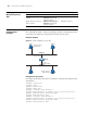
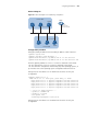
Host A belongs to VLAN 1, and Host D belongs to VLAN 2. Configure proxy ARP
on the device to enable the communication between the two hosts.
Network diagram
Figure 59 Network diagram for proxy ARP
Configuration procedure
# Configure Proxy ARP on the device to enable the communication between Host
A and Host D.
<Sysname> system-view
[Sysname] vlan 1
[Sysname-vlan1] vlan 2
[Sysname-vlan2] quit
[Sysname] interface vlan-interface 1
[Sysname-Vlan-interface1] ip address 192.168.10.99 255.255.255.0
[Sysname-Vlan-interface1] proxy-arp enable
[Sysname-Vlan-interface1] quit
[Sysname] interface vlan-interface 2
[Sysname-Vlan-interface2] ip address 192.168.20.99 255.255.255.0
[Sysname-Vlan-interface2] proxy-arp enable
[Sysname-Vlan-interface2] quit
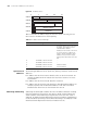
To do... Use the command... Remarks
Display whether proxy ARP is
enabled
display proxy-arp [
interface interface-type
interface-number ]
Available in any view
Display whether local proxy
ARP is enabled
display local-proxy-arp [
interface interface-type
interface-number ]
Available in any view
Vlan-int1
192.168.10.99/24
192.168.10.100/16
0000.0c94.36aa
192.168.20 .200/16
0000.0c94 .36dd
Device
Subnet B
Subnet A
Host A
Host B
Host C Host D
Vlan-int2
192 .168 .20 .99 /24