
3Com Switch 8800 Advanced Software V5 Configuration Guide


RIP Configuration Examples 285
-
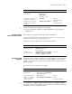
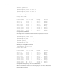
Peer 192.168.1.2 on Vlan-interface100
Destination/Mask Nexthop Cost Tag Flags Sec
10.0.0.0/8 192.168.1.2 1 0 RA 50
10.2.1.0/24 192.168.1.2 1 0 RA 16
10.1.1.0/24 192.168.1.2 1 0 RA 16
From the routing table, you can see RIP-2 uses classless subnet mask.
n
Since RIP-1 routing information has a long aging time, it will still exist until aged
out after RIP-2 is configured.
Configuring RIP Route
Redistribution
Network requirements
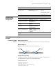
As shown in Figure 78, two RIP processes are running on Switch B, which
communicates with Switch A through RIP100 and with Switch C through RIP 200.
Configure route redistribution on Switch B, letting the two RIP processes
redistribute routes from each other. Set the cost of redistributed routes from RIP
200 to 3. Configure a filtering policy on Switch B to filter out the route
192.168.4.0/24 from RIP200, making the route not advertised to Switch A.
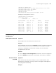
Network diagram
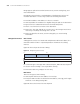
Figure 78 Network diagram for RIP route redistribution configuration
Configuration procedure
1 Configure an IP address for each interface (Omitted).
2 Configure basic RIP functions.
# Enable RIP 100 on Switch A.
<SwitchA> system-view
[SwitchA] rip 100
[SwitchA-rip-100] network 192.168.0.0
[SwitchA-rip-100] network 192.168.1.0
# Enable RIP 100 and RIP 200 on Switch B.
<SwitchB> system-view
[SwitchB] rip 100
[SwitchB-rip-100] network 192.168.1.0
[SwitchB-rip-100] quit
[SwitchB] rip 200
[SwitchB-rip-200] network 192.168.2.0
[SwitchB-rip-200] quit
# Enable RIP 200 on Switch C.
Eth1/1
Vlan-int100
192.168.1.2/24
Vlan-int200
192.168.2 .2/24
Vlan-int500
192.168 .4.1/24
Vlan-int200
192.168.2.1 /24
Vlan-int400
192.168.3.1/24
Vlan-int101
192.168.0.1/24 Vlan-int100
192.168 .1.3/24
Switch A
Switch B
Switch C
RIP 100 RIP 200
Eth1 /2
Eth1/1
Eth1 /2
Eth1/1