
3Com Switch 8800 Advanced Software V5 Configuration Guide

306 CHAPTER 30: OSPF CONFIGURATION
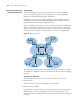
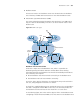
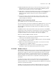
Figure 85 Virtual link application 1
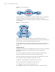
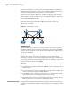
Another application of virtual links is to provide redundant links. If the backbone
area cannot maintain internal connectivity due to a physical link failure,
configuring a virtual link can guarantee logical connectivity in the backbone area,
as shown below.
Figure 86 Virtual link application 2
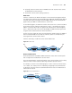
The virtual link between the two ABRs acts as a point-to-point connection.
Therefore, you can configure interface parameters such as hello packet interval on
the virtual link as they are configured on physical interfaces.
The two ABRs on the virtual link exchange OSPF packets with each other directly,
the OSPF routers in between simply convey these OSPF packets as normal IP
packets.
(Totally) Stub area
The ABR in a stub area does not distribute Type5 LSAs into the area, so the routing
table scale and amount of routing information in this area are reduced
significantly.
You can also configure the stub area as a Totally Stub area, where the ABR
advertises neither the routes of other areas nor the external routes.
Stub area configuration is optional, and not every area is qualified to be a stub
area. In general, a stub area resides on the border of the AS.
The ABR in a stub area generates a default route into the area.
Note the following when configuring a (totally) stub area:
■ The backbone area cannot be a (totally) stub area
■ The stub command must be configured on routers in a (totally) stub area
Area 0
Area 1
Area 2
ABRABR
Transit Area
Virtual Link
Area 0
Area 1
Virtual Link
R2
R1