
3Com Switch 8800 Advanced Software V5 Configuration Guide


OSPF Configuration Examples 345
Intra Area: 2 Inter Area: 3 ASE: 1 NSSA: 0
n
You can see on SwitchD an external route imported from the NSSA area.
Configuring OSPF DR
Election
Network requirements
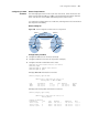
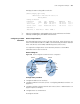
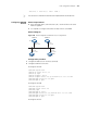
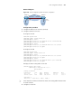
■ In the following figure, OSPF Switches A, B, C and D reside on the same
network segment.
■ It is required to configure SwitchA as the DR, SwitchC as the BDR.
Network diagram
Figure 106 Network diagram for OSPF DR election configuration
Configuration procedure
1 Configure IP addresses for interfaces (omitted)
2 Configure OSPF basic functions
# Configure SwitchA
<SwitchA> system-view
[Switch A] router id 1.1.1.1
[Switch A] ospf
[Switch A-ospf-1] area 0
[Switch A-ospf-1-area-0.0.0.0] network 196.1.1.0 0.0.0.255
[SwitchA-ospf-1-area-0.0.0.0] quit
[SwitchA-ospf-1] quit
# Configure SwitchB
<SwitchB> system-view
[SwitchB] router id 2.2.2.2
[SwitchB] ospf
[SwitchB-ospf-1] area 0
[SwitchB-ospf-1-area-0.0.0.0] network 196.1.1.0 0.0.0.255
[SwitchB-ospf-1-area-0.0.0.0] quit
[SwitchB-ospf-1] quit
# Configure SwitchC
Switch A Switch D
Switch B
Switch C
Vlan-int1
196.1.1.1/24
Vlan-int1
196.1.1.4/24
Vlan-int1
196.1.1.2/24
Vlan-int1
196.1.1 .3/24
DR
BDR