
3Com Switch 8800 Advanced Software V5 Configuration Guide


OSPF Configuration Examples 349
Network diagram
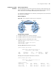
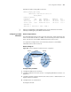
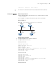
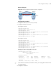
Figure 107 Network diagram for OSPF virtual link configuration
Configuration procedure
1 Configure IP addresses for interfaces (omitted)
2 Configure OSPF basic functions
# Configure SwitchA
<SwitchA> system-view
[SwitchA] ospf 1 router-id 1.1.1.1
[SwitchA-ospf-1] area 0
[SwitchA-ospf-1-area-0.0.0.0] network 10.0.0.0 0.255.255.255
[SwitchA-ospf-1-area-0.0.0.0] quit
[SwitchA-ospf-1] area 1
[SwitchA-ospf-1-area-0.0.0.1] network 192.168.1.0 0.0.0.255
[SwitchA-ospf-1-area-0.0.0.1] quit
# Configure SwitchB
<SwitchB> system-view
[SwitchB] ospf 1 router-id 2.2.2.2
[SwitchB-ospf-1] area 1
[SwitchB-ospf-1-area-0.0.0.1] network 192.168.1.0 0.0.0.255
[SwitchB-ospf-1-area-0.0.0.1] quit
[SwitchB-ospf-1] area 2
[SwitchB-ospf-1-area-0.0.0.2] network 172.16.0.0 0.0.255.255
[SwitchB-ospf-1-area-0.0.0.2] quit
# Display the OSPF routing table on SwitchA
[SwitchA] display ospf routing
OSPF Process 1 with Router ID 1.1.1.1
Routing Tables
Routing for Network
Destination Cost Type NextHop AdvRouter Area
10.0.0.0/8 1 Stub 10.1.1.1 1.1.1.1 0.0.0.0
192.168.1.0/24 1562 Stub 192.168.1.1 1.1.1.1 0.0.0.1
Total Nets: 2
Intra Area: 2 Inter Area: 0 ASE: 0 NSSA: 0
n
Since Area2 has no direct connection to Area0, the routing table of RouterA has
no route to Area2.
3 Configure a virtual link
Area 1
Vlan-int100
192.168.1 .2/24
Switch B
Vlan-int200
172.16.1.1/16
Area 2
Vlan-int100
192.168 .1.1/24
Switch A
Area 0
Vlan-int200
10.1.1.1/8
Virtual Link