
3Com Switch 8800 Advanced Software V5 Configuration Guide


364 CHAPTER 31: IPV6 OSPFV3 CONFIGURATION
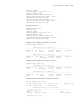
It is required to configure Area 2 as a stub area, reducing LSAs into the area
without affecting route reachability.
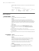
Network diagram
Figure 109 Network diagram for OSPFv3 area configuration
Configuration procedure
1 Configure IPv6 addresses for interfaces (omitted)
2 Configure OSPFv3 basic functions
# Configure Switch A.
<SwitchA> system-view
[SwitchA] ipv6
[SwitchA] ospfv3
[SwitchA-ospfv3-1] router-id 1.1.1.1
[SwitchA-ospfv3-1] quit
[SwitchA] interface vlan-interface 300
[SwitchA-Vlan-interface300] ospfv3 1 area 1
[SwitchA-Vlan-interface300] quit
[SwitchA] interface vlan-interface 200
[SwitchA-Vlan-interface200] ospfv3 1 area 1
[SwitchA-Vlan-interface200] quit
# Configure Switch B
<SwitchB> system-view
[SwitchB] ipv6
[SwitchB] ospfv3
[SwitchB-ospf-1] router-id 2.2.2.2
[SwitchB-ospf-1] quit
[SwitchB] interface vlan-interface 100
[SwitchB-Vlan-interface100] ospfv3 1 area 0
[SwitchB-Vlan-interface100] quit
[SwitchB] interface vlan-interface 200
[SwitchB-Vlan-interface200] ospfv3 1 area 1
[SwitchB-Vlan-interface200] quit
# Configure Switch C
<SwitchC> system-view
[SwitchC] ipv6
OSPFv3
Area 0
OSPFv3
Area 1
OSPFv3
Area 2
Switch A
Vlan-int100
2001::2/64
Vlan-int100
2001::1/64
Vlan-int300
2001:3::1/64
Vlan-int200
2001:1::2/64
Switch C
Vlan-int400
2001:2::1/64
Vlan-int400
2001:2::2/64
Switch B
Vlan-int200
2001:1::1/64
Switch D
Stub