
3Com Switch 8800 Advanced Software V5 Configuration Guide

386 CHAPTER 33: TUNNELING CONFIGURATION
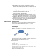
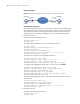
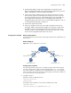
Network diagram
Figure 117 Network diagram for an automatic IPv4-compatible IPv6 tunnel
Configuration procedure
The following example shows how to configure an automatic IPv4-compatible IPv6
tunnel between Switch A and Switch B. No address needs to be specified for the
tunnel destination because the tunnel destination address can automatically be
obtained from the IPv4 address embedded in the IPv4-compatible IPv6 address.
1 Configure Switch A.
# Enable the IPv6 forwarding function.
<SwitchA> system-view
[SwitchA] ipv6
# Configure an IPv4 address for the interface VLAN-interface 12.
[SwitchA] vlan 12
[SwitchA-vlan12] port GigabitEthernet3/1/1
[SwitchA-vlan12] quit
[SwitchA] interface Vlan-interface 12
[SwitchA-Vlan-interface 12] ip address 2.1.1.1 255.0.0.0
[SwitchA-Vlan-interface 12] quit
# Configure an automatic IPv4-compatible IPv6 tunnel.
[SwitchA] interface tunnel 0/0/1
[SwitchA-Tunnel0/0/1] ipv6 address ::2.1.1.1/96
[SwitchA-Tunnel0/0/1] source Vlan-interface 12
[SwitchA-Tunnel0/0/1] tunnel-protocol ipv6-ipv4 auto-tunnel
# Configure a link aggregation group and set the service type to tunnel.
[SwitchA] link-aggregation group 1 mode manual
[SwitchA] link-aggregation group 1 service-type tunnel
[SwitchA] interface GigabitEthernet 3/1/2
[SwitchA-GigabitEthernet3/1/2] stp disable
[SwitchA-GigabitEthernet3/1/2] port link-aggregation group 1
[SwitchA-GigabitEthernet3/1/2] quit
# Reference link aggregation group 1 and enable expedite termination in tunnel
interface view.
[SwitchA] interface tunnel 0/0/1
[SwitchA-Tunnel0/0/1] aggregation-group 1
[SwitchA-Tunnel0/0/1] expediting enable
[SwitchA-Tunnel0/0/1] expediting subnet 2.1.1.0 255.0.0.0
[SwitchA-Tunnel0/0/1] quit
2 Configure Switch B
# Enable the IPv6 forwarding function.
<SwitchB> system-view
[SwitchB] ipv6
Vlan-int100
2.1 .1.1/8
Vlan-int100
2.1.1.2/8
Tunnel 0
::2.1.1.1/96
Tunnel0
::2.1.1.2/96
Dual stack
Switch A Switch B
Dual stack
IPv4 netwok