
3Com Switch 8800 Advanced Software V5 Configuration Guide

Configuring IPv4 over IPv4 Tunnel 397
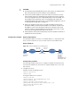
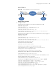
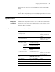
Network diagram
Figure 120 Network diagram for an IPv4 over IPv4 tunnel
Configuration procedure
1 Configure Switch A
# Configure an IPv4 address for the interface VLAN-interface 100.
<SwitchA> system-view
[SwitchA] vlan 100
[SwitchA-vlan100] port GigabitEthernet 1/1/1
[SwitchA-vlan100] quit
[SwitchA] interface vlan-interface 100
[SwitchA-Vlan-interface100] ip address 10.1.1.1 255.255.255.0
[SwitchA-Vlan-interface100] quit
# Configure an IPv4 address for the interface VLAN-interface 101 (the physical
interface of the tunnel).
[SwitchA] vlan 101
[SwitchA-vlan101] port GigabitEthernet 1/1/2
[SwitchA-vlan101] quit
[SwitchA] interface vlan-interface 101
[SwitchA-Vlan-interface101] ip address 192.13.2.1 255.255.255.0
[SwitchA-Vlan-interface101] quit
# Create the interface Tunnel 1/0/0.
[SwitchA] interface tunnel 1/0/0
# Configure an IPv4 address for the interface Tunnel 1/0/0.
[SwitchA-Tunnel1/0/0] ip address 10.1.2.1 255.255.255.0
# Configure the tunnel encapsulation mode.
[SwitchA-Tunnel1/0/0] tunnel-protocol ipv4-ipv4
# Configure a source address for the interface Tunnel 1/0/0.
[SwitchA-Tunnel1/0/0] source 192.13.2.1
# Configure a source address for the interface Tunnel 1/0/0 (IP address of the
interface VLAN-interface 101 of Switch B).
[SwitchA-Tunnel1/0/0] destination 131.108.5.2
# Configure a link aggregation group and set the service type to tunnel.
[SwitchA] link-aggregation group 1 mode manual
[SwitchA] link-aggregation group 1 service-type tunnel
[SwitchA] interface GigabitEthernet 1/1/3
[SwitchA-GigabitEthernet1/1/3] stp disable
[SwitchA-GigabitEthernet1/1/3] port link-aggregation group 1
[SwitchA-GigabitEthernet1/1/3] quit
Vlan-int101
192.13.2.1/24
Vlan-int100
10.1.3 .1/24
Vlan-int100
10.1.1.1/24
Switch A
IPv4 netwok
IPv4
Group 1
Tunnel 1/0 /0
10 .1. 2.1/24
Vlan-int101
131.108.5.2/24
Tunnel2/0/0
10.1.2.2/24
IPv4
Group 2
Switch B