
3Com Switch 8800 Advanced Software V5 Configuration Guide


Configuring Tunnel Hybrid Insertion 401
■ On PC A, the next hop gateway address of the route to PC B (6666::6/64) is set
to 1000::1, and on PC B, the next hop gateway address of the route to PC A
(1000::2/64) s is set to 6666::9.
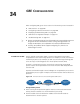
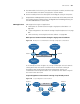
Network diagram
Figure 121 Network diagram for tunnel hybrid insertion
Configuration procedure
1 Configure Switch A.
<SwitchA> system-view# Enable the IPv6 forwarding function.
[SwitchA] ipv6
# Configure an IPv4 address for the interface VLAN-interface 12.
[SwitchA] vlan 12
[SwitchA-vlan12] port GigabitEthernet4/1/3
[SwitchA] interface Vlan-interface 12
[SwitchA-Vlan-interface12] ipv6 address 1000::1 64
[SwitchA-Vlan-interface12] quit
# Configure a link aggregation group and set the service type to tunnel.
[SwitchA] link-aggregation group 1 mode manual
[SwitchA] link-aggregation group 1 service-type tunnel
[SwitchA-GigabitEthernet4/1/1] stp disable
[SwitchA-GigabitEthernet4/1/1] port link-aggregation group 1
[SwitchA-GigabitEthernet4/1/1] quit
# Configure the tunnel source interface - VLAN-interface 10 on the IPv4 card.
[SwitchA] vlan 10
[SwitchA-vlan10] port GigabitEthernet 3/1/1
[SwitchA] interface Vlan-interface 10
[SwitchA-Vlan-interface10] ip address 1.1.1.1 24
[SwitchA-Vlan-interface10] quit
# Configure an IPv6 manually configured tunnel on the interface Tunnel 4/0/0.
[SwitchA] interface Tunnel 4/0/0
[SwitchA-Tunnel4/0/0] tunnel-protocol ipv6-ipv4
[SwitchA-Tunnel4/0/0] ipv6 address 3333::1 64
[SwitchA-Tunnel4/0/0] source Vlan-interface 10
Vlan-int10
1.1.1 .1/24
Switch A
IPv4 network
IPv6
network
Tunnel4 /0/0
Vlan-int10
1.1.1.2/24
Tunnel3/0/0
IPv6
network
Switch B
PC A
1000 ::2/64
PC B
6666 ::6/64