
3Com Switch 8800 Advanced Software V5 Configuration Guide

GRE Tunnel Configuration Example 413
[Sysname2] interface tunnel 4/0/1
# Configure an IPv4 address for interface Tunnel 4/0/1.
[Sysname2-Tunnel4/0/1] ip address 10.1.2.2 255.255.255.0
# Configure the tunnel encapsulation mode.
[Sysname2-Tunnel4/0/1] tunnel-protocol gre
# Configure the source address for interface tunnel4/0/1 (IP address of the VLAN
interface to which GigabitEthernet 4/1/2 belongs).
[Sysname2-Tunnel4/0/1] source vlan-interface 101
# Configure the destination address for interface Tunnel 4/0/1 (IP address of the
VLAN interface to which GigabitEthernet 4/1/2 of Switch 1 belongs). Moreover,
enable the expediting function.
[Sysname2-Tunnel4/0/1] destination 192.13.2.1
[Sysname2-Tunnel4/0/1] expediting enable
[Sysname2-Tunnel4/0/1] quit
# Create service loop group 1, setting the configuration mode to manual and the
service type to tunnel.
[Sysname2] link-aggregation group 1 mode manual
[Sysname2] link-aggregation group 1 service-type tunnel
# Add interface GigabitEthernet 4/1/3 to service loop group 1.
[Sysname2] interface GigabitEthernet 4/1/3
[Sysname2-GigabitEthernet4/1/3] stp disable
[Sysname2-GigabitEthernet4/1/3] port link-aggregation group 1
# Apply service loop group 1 to the tunnel in tunnel interface view.
[Sysname2-GigabitEthernet4/1/3] quit
[Sysname2] interface tunnel 4/0/1
[Sysname2-Tunnel4/0/1] aggregation-group 1
[Sysname2-Tunnel4/0/1] quit
# Configure a static route from Switch 2 through interface Tunnel 4/0/1 to
Group1.
[Sysname2] ip route-static 10.1.1.0 255.255.255.0 Tunnel 4/0/1
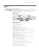
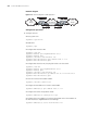
GRE IPv6 over IPv4
Tunnel Configuration
Example
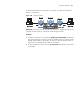
Network requirements
Switch 1 and Switch 2 are interconnected through an IPv4 network. Two IPv6
subnets Group1 and Group2 are interconnected through a GRE tunnel between
Switch 1 and Switch 2.