
3Com Switch 8800 Advanced Software V5 Configuration Guide

454 CHAPTER 35: BGP CONFIGURATION
Reply from 9.1.2.1: bytes=56 Sequence=3 ttl=254 time=47 ms
Reply from 9.1.2.1: bytes=56 Sequence=4 ttl=254 time=46 ms
Reply from 9.1.2.1: bytes=56 Sequence=5 ttl=254 time=47 ms
--- 9.1.2.1 ping statistics ---
5 packet(s) transmitted
5 packet(s) received
0.00% packet loss
round-trip min/avg/max = 15/37/47 ms
BGP Load Balancing and
MED Attribute
Configuration
Network requirements
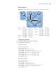
■ Configure BGP on all switches; Switch A is in ASwitch 7750 Family8, Switch B
and C in ASwitch 7750 Family9.
■ Between Switch A and B, Switch A and C are EBGP connections, and IBGP runs
between Switch B and C.
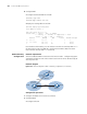
Network diagram
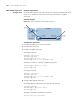
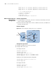
Figure 148 Network diagram for BGP path selection configuration
Configuration procedure
1 Configure IP addresses for interfaces (omitted)
2 Configure BGP connections
# Configure SwitchA
<SwitchA> system-view
[SwitchA] bgp 65008
[SwitchA-bgp] router-id 1.1.1.1
[SwitchA-bgp] peer 200.1.1.1 as-number 65009
[SwitchA-bgp] peer 200.1.2.1 as-number 65009
# Advertise route 8.0.0.0/8 to BGP routing table.
[SwitchA-bgp] network 8.0.0.0 255.0.0.0
[SwitchA-bgp] quit
# Configure SwitchB
<SwitchB> system-view
[SwitchB] bgp 65009
[SwitchB-bgp] router-id 2.2.2.2
Vlan-int200
200.1.1.2/24
Switch A
AS 65008
Vlan-int100
8.1.1.1/8
Vlan-int400
9.1.1.2/24
Vlan-int300
200.1.2.1/24
Vlan-int200
200.1.1.1/24
Switch B
Switch C
AS 65009
Vlan-int300
200.1.2.2/24
Vlan-int400
9.1.1.1/24
EBGP
EBGP
IBGP