
3Com Switch 8800 Advanced Software V5 Configuration Guide

BGP Configuration Examples 459
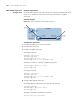
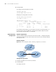
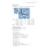
Network diagram
Figure 150 Network diagram for BGP confederation configuration (on switches)
Configuration procedure
1 Configure IP addresses for interfaces (omitted)
2 Configure BGP confederation
# Configure SwitchA
<SwitchA> system-view
[SwitchA] bgp 65001
[SwitchA-bgp] router-id 1.1.1.1
[SwitchA-bgp] confederation id 200
[SwitchA-bgp] confederation peer-as 65002 65003
[SwitchA-bgp] peer 10.1.1.2 as-number 65002
[SwitchA-bgp] peer 10.1.1.2 next-hop-local
[SwitchA-bgp] peer 10.1.2.2 as-number 65003
[SwitchA-bgp] peer 10.1.2.2 next-hop-local
[SwitchA-bgp] quit
# Configure SwitchB
<SwitchB> system-view
[SwitchB] bgp 65002
[SwitchB-bgp] router-id 2.2.2.2
[SwitchB-bgp] confederation id 200
[SwitchB-bgp] confederation peer-as 65001 65003
[SwitchB-bgp] peer 10.1.1.1 as-number 65001
[SwitchB-bgp] quit
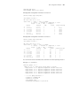
Device Interface IP address Device Interface IP address
Switch A Vlan-int100 200.1.1.1/24 Switch D Vlan-int100 10.1.3.2/24
Vlan-int200 10.1.1.1/24 Vlan-int200 10.1.5.1/24
Vlan-int300 10.1.2.1/24 Switch E Vlan-int100 10.1.4.2/24
Vlan-int400 10.1.3.1/24 Vlan-int200 10.1.5.2/24
Vlan-int500 10.1.4.1/24 Switch F Vlan-int100 9.1.1.1/24
Switch B Vlan-int100 10.1.1.2/24 Vlan-int200 200.1.1.2/24
Switch C Vlan-int100 10.1.2.2/24
Switch F
Switch A
Switch D
Switch E
AS 200
AS 100
Vlan-int100
Switch B
Switch C
AS 65002
AS 65003
Vlan-int200
Vlan-int100
AS 65001
Vlan-int200
Vl
an
-i
nt
30
0
Vlan-int400
Vlan-int500
Vlan-int100
Vlan-int100
Vlan-int200
Vlan-int100
Vlan-int100
Vlan-int200