
3Com Switch 8800 Advanced Software V5 Configuration Guide


462 CHAPTER 35: BGP CONFIGURATION
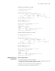
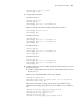
Network diagram
Figure 151 Network diagram for BGP route reflector configuration
Configuration procedure
1 Configure IP addresses for interfaces (omitted)
2 Configure BGP connections
# Configure SwitchA
<SwitchA> system-view
[SwitchA] bgp 100
[SwitchA-bgp] router-id 1.1.1.1
[SwitchA-bgp] peer 192.1.1.2 as-number 200
# Advertise network 1.0.0.0/8 to the BGP routing table.
[SwitchA-bgp] network 1.0.0.0
[SwitchA-bgp] quit
# Configure SwitchB
<SwitchB> system-view
[SwitchB] bgp 200
[SwitchB-bgp] router-id 2.2.2.2
[SwitchB-bgp] peer 192.1.1.1 as-number 100
[SwitchB-bgp] peer 193.1.1.1 as-number 200
[SwitchB-bgp] peer 193.1.1.1 next-hop-local
[SwitchB-bgp] quit
# Configure SwitchC
<SwitchC> system-view
[SwitchC] bgp 200
[SwitchC-bgp] router-id 3.3.3.3
[SwitchC-bgp] peer 193.1.1.2 as-number 200
[SwitchC-bgp] peer 194.1.1.2 as-number 200
[SwitchC-bgp] quit
# Configure SwitchD
<SwitchD> system-view
[SwitchD] bgp 200
[SwitchD-bgp] router-id 4.4.4.4
Vlan-int200
192.1.1.1/24
Switch A
AS 100
Vlan-int200
192.1.1.2/24
Vlan-int100
1.1.1.1/8
Vlan-int300
193.1.1.2/24
Vlan-int400
194.1.1.2/24
Vlan-int400
194.1.1 .1/24
Vlan-int300
193.1.1.1/24
Switch C
Switch B
Switch D
AS 200
Router
Reflector