
3Com Switch 8800 Advanced Software V5 Configuration Guide


464 CHAPTER 35: BGP CONFIGURATION
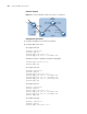
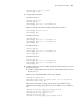
Network diagram
Figure 152 Network diagram for BGP path selection configuration (on switches)
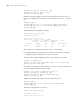
Configuration procedure
1 Configure IP addresses for interfaces (omitted).
2 Configure OSPF on Switch B, C, and D.
# Configure Switch B
<SwitchB> system-view
[SwitchB] ospf
[SwitchB-ospf] area 0
[SwitchB-ospf-1-area-0.0.0.0] network 192.1.1.0 0.0.0.255
[SwitchB-ospf-1-area-0.0.0.0] network 194.1.1.0 0.0.0.255
[SwitchB-ospf-1-area-0.0.0.0] quit
[SwitchB-ospf-1] quit
# Configure Switch C
<SwitchC> system-view
[SwitchC] ospf
[SwitchC-ospf] area 0
[SwitchC-ospf-1-area-0.0.0.0] network 193.1.1.0 0.0.0.255
[SwitchC-ospf-1-area-0.0.0.0] network 195.1.1.0 0.0.0.255
[SwitchC-ospf-1-area-0.0.0.0] quit
[SwitchC-ospf-1] quit
# Configure Switch D
<SwitchD> system-view
[SwitchD] ospf
[SwitchD-ospf] area 0
[SwitchD-ospf-1-area-0.0.0.0] network 194.1.1.0 0.0.0.255
[SwitchD-ospf-1-area-0.0.0.0] network 195.1.1.0 0.0.0.255
Device Interface IP address Device Interface IP address
Switch A Vlan-int101 1.0.0.0/8 Switch D Vlan-int400 195.1.1.1/24
Vlan-int100 192.1.1.1/24 Vlan-int300 194.1.1.1/24
Vlan-int200 193.1.1.1/24 Switch C Vlan-int400 195.1.1.2/24
Switch B Vlan-int100 192.1.1.2/24 Vlan-int200 193.1.1.2/24
Vlan-int300 194.1.1.2/24
Switch A
AS 100
Vlan-int101
Switch C
AS 200
Vlan-int200
Switch B
Switch D
Vlan-int100
Vlan-int200
Vlan-int400
Vlan-int400
Vlan-int300
Vlan-int300Vlan-int100