
3Com Switch 8800 Advanced Software V5 Configuration Guide


498 CHAPTER 37: MULTICAST OVERVIEW
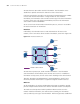
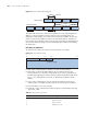
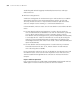
Figure 158 IPv4-to-MAC address mapping
The high-order four bits of a multicast IPv4 address are 1110, indicating that this
address is a multicast address, and only 23 bits of the remaining 28 bits are
mapped to a MAC address, so five bits of the multicast IPv4 address are lost. As a
result, 32 multicast IPv4 addresses map to the same MAC address. Therefore, in
Layer 2 multicast forwarding, a device may receive some multicast data addressed
for other IPv4 multicast groups, and such redundant data needs to be filtered by
the upper layer.
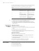
IPv6 Multicast Addresses
As defined in RFC 4291, the format of an IPv6 multicast is as follows:
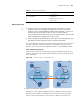
Figure 159 IPv6 multicast format
■ 0xFF: 8 bits, indicating that this address is an IPv6 multicast address.
■ Flags: 4 bits, of which the high-order bits are reserved and set to 0; the
lowest-order bit is the Transient (T) flag. When set to 0, the T flag indicates a
permanently-assigned (well-known) multicast address assigned by IANA; when
set to 1, the T flag indicates a transient, or dynamically assigned multicast
address.
■ Scope: 4 bits, indicating the scope of the IPv6 internetwork for which the
multicast traffic is intended. Possible values of this field are given in
Table 27.
■ Reserved: 80 bits, all set to 0 currently.
■ Group ID: 112 bits, identifying the multicast group. For details about this field,
refer to RFC 3306.
Tabl e 27 Values of the Scope field
Value Meaning
0, 3, F Reserved
1 Node-local scope
2 Link-local scope
4 Admin-local scope
XXXX X
XXXX XXXX XXXX XXXX XXXX XXXX1110 XXXX
0XXX XXXX XXXX XXXX XXXX XXXX0000 0001 0000 0000 0101 1110
32-bit IP address
48-bit MAC address
5 bits lost
25-bit MAC address prefix
Ă
Ă
23 bits
mapped
Group ID (112 bits)
0xFF Flags Scope
0 7 11 15 31