
3Com Switch 8800 Advanced Software V5 Configuration Guide


506 CHAPTER 38: MULTICAST ROUTING AND FORWARDING CONFIGURATION
means that the interface on which the packet actually arrived is not the RPF
interface. The RPF check fails and the packet is discarded.
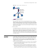
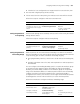
■ A multicast packet from Source arrives to POS5/1/1 of Switch C, and the
corresponding forwarding entry does not exist in the multicast forwarding
table of Switch C. The device performs an RPF check, and finds in its unicast
routing table that the outgoing interface to 192.168.0.0/24 is the interface on
which the packet actually arrived. The RPF check succeeds and the packet is
forwarded.
Multicast Static Route If the topology structure of a multicast network is the same as that of a unicast
network, receivers can receive multicast data via unicast routes. However, the
topology structure of a multicast network may differ from that of a unicast
network, and some devices may support only unicast but not multicast. In this
case, you can configure multicast static routes to provide multicast transmission
paths that are different from those for unicast traffic. Note the following two
points:
■ A multicast static route only affects RPF checks, rather than guides multicast
forwarding, so it is also called an RPF static route.
■ A multicast static route is effective on the multicast device on which it is
configured, and will not be broadcast throughout the network or injected to
other devices.
A multicast static route is an important basis for RPF checks. With a multicast static
route configured on a device, the device searches the unicast routing table and the
multicast static routing table simultaneously in a RPF check, chooses the optimal
unicast RPF route and the optimal multicast static route respectively from the
routing tables, and uses one of them as the RPF route after comparison.
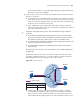
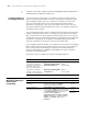
Figure 163 Multicast static route
As shown in Figure 163, when no multicast static route is configured, Switch C’s
RPF neighbor on the path back to Source is Switch A and the multicast
information from Source travels along the path from Switch A to Switch C, which
is the unicast route between the two devices; with a static route configured on
Switch C and Switch B as Switch C’s RPF neighbor on the path back to Source, the
Receiver
Switch A
Switch B
Switch C
POS5/1/1
POS5/1/2
1.1.1.1/24
POS5/1/1
Multicast packets
Source
192.168.0 .1/24
Receiver
POS5/1/2
1.1.1.2/24
Multicast static route
Destination /Mask
Multicast Routing Table Static on Switch C
192.168.0.0/24
Interface
POS5/1/2
RPF neighbor/Mask
1.1.1.1/24