
3Com Switch 8800 Advanced Software V5 Configuration Guide


IGMP Configuration Examples 535
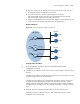
■ Switch A connects to N1 through Vlan-interface100, and to other devices in
the PIM-DM network through Vlan-interface101.
■ Switch B and Switch C connect to N2 through their respective
Vlan-interface200, and to other devices in the PIM-DM network through
Vlan-interface201 and Vlan-interface202 respectively.
■ IGMPv2 is required between Switch A and N1. IGMPv2 is required between the
other two switches and N2, with Switch B as the IGMP querier.
Network diagram
Figure 168 Network diagram for IGMP configuration
Configuration procedure
n
In the configuration procedure, only the commands related to IGMP
configurations are listed.
1 Configure the IP addresses of the switch interfaces and configure a unicast routing
protocol.
Configure the IP address and subnet mask of each interface as per Figure 168. The
detailed configuration steps are omitted here.
Configure the OSPF protocol for interoperation among the switches. Ensure the
network-layer interoperation among Switch A, Switch B and Switch C on the
PIM-DM network and dynamic update of routing information among the switches
through a unicast routing protocol. The detailed configuration steps are omitted
here.
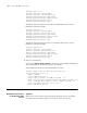
2 Enable IP multicast routing, and enable IGMP on the host-side interfaces.
# Enable IP multicast routing on Switch A, and enable IGMP (version 2) and
PIM-DM on Vlan-interface100.
Switch A
Switch B
Switch C
Querier
PIM network
Ethernet Ethernet
N1
N2
Receiver
Receiver
Host A
Host B
Host C
Host D
Vlan-int100
10 .110 .1. 1/ 24
Vlan-int200
10 .110 .2. 1/ 24
Vlan-int200
10 .110 .2. 2/ 24
Vlan-int101
Vlan-int201
Vlan-int202