
3Com Switch 8800 Advanced Software V5 Configuration Guide

556 CHAPTER 41: IGMP SNOOPING CONFIGURATION
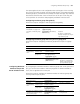
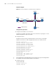
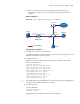
Network diagram
Figure 171 Network diagram for simulated joining configuration
Configuration procedure
1 Configure the IP address of each interface
Configure an IP address and subnet mask for each interface as per Figure 171. The
detailed configuration steps are omitted.
2 Configure Router A
# Enable IP multicast routing, enable PIM-SM on each interface, and enable
IGMPv3 on Ethernet1/1/1 and configure Ethernet1/1/2 as C-BSR and C-RP.
<RouterA> system-view
[RouterA] multicast routing-enable
[RouterA] interface ethernet 1/1/1
[RouterA-Ethernet1/1/1] igmp enable
[RouterA-Ethernet1/1/1] igmp version 3
[RouterA-Ethernet1/1/1] pim sm
[RouterA-Ethernet1/1/1] quit
[RouterA] interface ethernet 1/1/2
[RouterA-Ethernet1/1/2] pim sm
[RouterA-Ethernet1/1/2] quit
[RouterA] pim
[RouterA-pim] c-bsr ethernet 1/1/2
[RouterA-pim] c-rp ethernet 1/1/2
[RouterA-pim] quit
n
The configurations mentioned above are for reference only. Specific configurations
are subject to the actual implementations of the devices.
3 Configure Switch A
# Create VLAN 100.
<SwitchA> system-view
[SwitchA] vlan 100
Source
1.1.1.1/24
Multicast packets
Router A Switch A
Receiver
Receiver
Host B
Host A
Host C
Eth1/1 /3
Eth1/1 /1
Eth1 /1/2
IGMP querier
Eth1 /1/4
Eth1 /1/1
10 .1 .1. 1/ 24
Eth1/1/2
1.1.1.2/24