
3Com Switch 8800 Advanced Software V5 Configuration Guide

IGMP Snooping Configuration Examples 557
# Assign Ethernet1/1/1 through Ethernet1/1/4 to this VLAN.
[SwitchA-vlan100] port ethernet 1/1/1 to ethernet 1/1/4
[SwitchA-vlan100] quit
# Enable IGMP Snooping in VLAN 100 and set the version to 3.
[SwitchA] igmp-snooping
[SwitchA-igmp-snooping] quit
[SwitchA] vlan 100
[SwitchA-vlan100] igmp-snooping enable
[SwitchA-vlan100] igmp-snooping version 3
[SwitchA-vlan100] quit
# Enable simulated (S, G) joining on Ethernet 1/1/2 and Ethernet 1/1/3 respectively.
[SwitchA] interface ethernet 1/1/2
[SwitchA-Ethernet1/1/2] igmp-snooping host-join 232.1.1.1 source-ip
1.1.1.1 vlan 100
[SwitchA-Ethernet1/1/2] quit
[SwitchA] interface ethernet 1/1/3
[SwitchA-Ethernet1/1/3] igmp-snooping host-join 232.1.1.1 source-ip
1.1.1.1 vlan 100
[SwitchA-Ethernet1/1/3] quit
IGMP Snooping Querier
Configuration
Network requirements
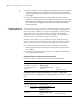
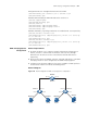
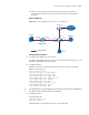
■ As shown in Figure 172, in a Layer-2 network environment without Layer-3
devices, Switch C is connected to the multicast source (Source) through
Ethernet1/1/2. At least one receiver is attached to Switch B and Switch C
respectively.
■ All the receiver hosts run IGMPv2. Switch A, Switch B, and Switch C run IGMP
Snooping. Switch A is to be configured as the IGMP Snooping querier.
■ Configure a non-all-zero IP address as the source IP address of IGMP queries to
ensure normal creation of multicast forwarding entries.
Network diagram
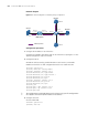
Figure 172 Network diagram for IGMP Snooping querier configuration
Source
1.1.1 .1/24
Host A
Receiver
Switch C
Switch A
Switch B
Host B
Receiver
Host C
Receiver
Querier
Eth1 /1/3 Eth1/1/1
Eth1/1/3 Eth1 /1/3
Eth1/1/1 Eth1/1 /2 Eth1/1/1 Eth1/1 /2