
3Com Switch 8800 Advanced Software V5 Configuration Guide


PIM Configuration Examples 597
Protocol: pim-dm, UpTime: 00:03:27, Expires: never
2: Vlan-interface101
Protocol: pim-dm, UpTime: 00:03:27, Expires: never
3: Vlan-interface102
Protocol: pim-dm, UpTime: 00:03:27, Expires: never
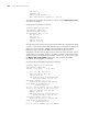
PIM-SM Configuration
Example
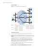
Network requirements
■ Receivers receive VOD information through multicast. The receiver groups of
different organizations form stub networks, and one or more receiver hosts
exist in each stub network. The entire PIM domain operates in the sparse mode
(not divided into different BSR admin-scope regions).
■ Host A and Host C are multicast receivers in two stub networks.
■ Switch D connects to the network that comprises the multicast source (Source)
through VLAN-interface 300.
■ Switch A connects to stub network N1 through VLAN-interface 100, and to
Switch D and Switch E through VLAN-interface 101 and VLAN-interface 102
respectively.
■ Switch B and Switch C connect to stub network N2 through their respective
VLAN-interface 200, and to Switch E through VLAN-interface 103 and
VLAN-interface 104 respectively.
■ Switch E connects to Switch A, Switch B, Switch C and Switch D, and its
VLAN-interface 102 interface acts a C-BSR and a C-RP, with the range of
multicast groups served by the C-RP being 225.1.1.0/24.
Network diagram
Figure 184 Network diagram for PIM-SM domain configuration (on switches)
Device Interface IP address Device Interface IP address
Ethernet
EthernetEthernet
Source
10.110 .5.100/24
PIM-SM
Switch A
Switch B
Switch C
Switch D
Receive
r
Host A
Host B
Host C
Host D
Receive
r
N1N2
Switch E
Vlan-int100
Vlan-int200
Vlan-int200
Vlan-int300
Vlan-int102
Vlan-int102
V
la n
-
i
nt
1
0
1
V
l
a
n
-
i
n
t
1
01
Vlan-int103
Vlan-int103
Vlan-int104
Vlan-int104
Vlan-int105
Vlan-int105