
3Com Switch 8800 Advanced Software V5 Configuration Guide


602 CHAPTER 42: PIM CONFIGURATION
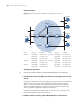
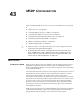
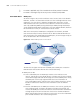
Network diagram
Figure 185 Network diagram for PIM-SSM configuration (on switches)
Configuration procedure
n
Only the commands related to the PIM-SMM configuration are listed below.
1 Configure the interface IP addresses and unicast routing protocol for each
switch
Configure the OSPF protocol for interoperation among the switches in the PIM-SM
domain. Ensure the network-layer interoperation among Switch A, Switch B,
Switch C, Switch D and Switch E in the PIM-SM domain and enable dynamic
update of routing information among the switches through a unicast routing
protocol. Detailed configuration steps are omitted here.
Configure the IP address and subnet mask for each interface as per Figure 185.
Detailed configuration steps are omitted here.
2 Enable IP multicast routing, and enabling PIM-SM on each interface
Device Interface IP address Device Interface IP address
Switch A Vlanint100 10.110.1.1/24 Switch D Vlanint300 10.110.5.1/24
Vlanint101 192.168.1.1/24 Vlanint101 192.168.1.2/24
Vlanint102 192.168.9.1/24 Vlanint105 192.168.4.2/24
Switch B Vlanint200 10.110.2.1/24 Switch E Vlanint104 192.168.3.2/24
Vlanint103 192.168.2.1/24 Vlanint103 192.168.2.2/24
Switch C Vlanint200 10.110.2.2/24 Vlanint102 192.168.9.2/24
Vlanint104 192.168.3.1/24 Vlanint105 192.168.4.1/24
Ethernet
EthernetEthernet
Source
10.110 .5.100/24
PIM-SM
Switch A
Switch B
Switch C
Switch D
Receive
r
Host A
Host B
Host C
Host D
Receive
r
N1N2
Switch E
Vlan-int100
Vlan-int200
Vlan-int200
Vlan-int300
Vlan-int102
Vlan-int102
V
l
a
n
-
i
nt
1
0
1
V
l
a
n
-
i
n
t
1
0
1
Vlan-int103
Vlan-int103
Vlan-int104
Vlan-int104
Vlan-int105
Vlan-int105