
3Com Switch 8800 Advanced Software V5 Configuration Guide

624 CHAPTER 43: MSDP CONFIGURATION
Configuration procedure
n
Only the commands related to the MSDP configuration leveraging a BGP route are
listed in this example.
1 Configure the interface IP addresses and unicast routing protocol for each switch
Configure OSPF for interconnection between devices in each PIM-SM domain.
Ensure the network-layer interoperation among Switch A, Switch B and Switch C
in PIM-SM 1, the network-layer interoperation between Switch D and Switch E in
PIM-SM 2, and the network-layer interoperation between Switch F and Switch G
in PIM-SM 3, and ensure the dynamic update of routing information between the
devices in each PIM-SM domain through a unicast routing protocol. Detailed
configuration steps are omitted.
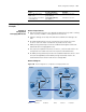
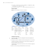
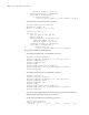
Configure the IP address and subnet mask for each interface as per Figure 190.
Detailed configuration steps are omitted.
2 Enable IP multicast routing, and enable PIM-SM on each interface
# Enable IP multicast routing on Switch C, and enable PIM-SM on each interface.
<SwitchC> system-view
[SwitchC] multicast routing-enable
[SwitchC] interface vlan-interface 100
[SwitchC-Vlan-interface100] pim sm
[SwitchC-Vlan-interface100] quit
[SwitchC] interface vlan-interface 200
[SwitchC-Vlan-interface200] pim sm
[SwitchC-Vlan-interface200] quit
[SwitchC] interface vlan-interface 101
[SwitchC-Vlan-interface101] pim sm
The configuration on Switch A, Switch B, Switch D, Switch E, Switch F and Switch
G is similar to the configuration on Switch C.
# Configure BSR boundary on Switch C.
[SwitchC-Vlan-interface101] pim bsr-boundary
[SwitchC-Vlan-interface101] quit
The configuration on Switch D and Switch F is similar to the configuration on
Switch C.
3 Configure Loopback 0 and the position of C-BSR, and C-RP
# Configure the position of Loopback0, C-BSR, and C-RP on Switch C.
Switch C Vlan-int100 10.110.1.1/24 Switch D Vlan-int300 10.110.4.1/24
Vlan-int200 10.110.2.1/24 Vlan-int102 192.168.3.1/24
Vlan-int101 192.168.1.1/24 Vlan-int101 192.168.1.2/24
Loop0 1.1.1.1/32 Loop0 2.2.2.2/32
Switch F Vlan-int400 10.110.3.1/24
Vlan-int102 192.168.3.2/24
Loop0 3.3.3.3/32