
3Com Switch 8800 Advanced Software V5 Configuration Guide


628 CHAPTER 43: MSDP CONFIGURATION
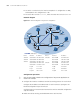
■ On Switch C and Switch F, the interface Loopback 1 is configured as a C-BSR,
and Loopback 10 is configured as a C-RP.
■ The router ID of Switch C is 1.1.1.1, while the router ID of Switch F is 2.2.2.2.
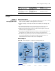
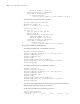
Network diagram
Figure 191 Network diagram for anycast RP configuration
Configuration procedure
n
Only the commands related to the configuration of Anycast RP application are
listed in this example.
1 Configure the interface IP addresses and unicast routing protocol for each switch
Configure the IP address and subnet mask for each interface as per Figure 191.
Detailed configuration steps are omitted.
Configure OSPF for interconnection between the switches. Detailed configuration
steps are omitted.
2 Enable IP multicast routing, and enable PIM-SM on each interface
Device Interface IP address Device Interface IP address
Switch A Vlan-int103 10.110.1.2/24 Switch D Vlan-int300 10.110.4.1/24
Switch B Vlan-int100 10.110.2.2/24 Vlan-int102 192.168.3.1/24
Switch C Vlan-int103 10.110.1.1/24 Vlan-int101 192.168.1.2/24
Vlan-int100 10.110.2.1/24 Switch F Vlan-int200 10.110.3.1/24
Vlan-int101 192.168.1.1/24 Vlan-int102 192.168.3.2/24
Loop0 1.1.1.1/32 Loop0 2.2.2.2/32
Loop1 3.3.3.3/32 Loop1 4.4.4.4/32
Loop10 10.1.1.1/32 Loop10 10.1.1.1/32
Source 2
Source 3
Receiver
Receiver
Receiver
Switch A
Switch B
Switch C
Switch D Switch E
Switch F
Switch G
Loop0
L
o
o
p
1
Loop10
L
o
o
p1
Loop10
Loop0
PIM-SM
MSDP peers
Vlan-int101
Vlan-int101
V
l
an
-
i
n
t
1
0
0
V
l
a
n
-
in
t1
0
0
Vlan-int103
Vlan-int103
Vlan-int102
Vlan-int102
Vlan-int300
Vlan-int200
Source 1
10.110.5.100/24