
3Com Switch 8800 Advanced Software V5 Configuration Guide


632 CHAPTER 43: MSDP CONFIGURATION
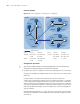
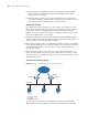
Network diagram
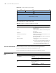
Figure 192 Network diagram for static RPF peer configuration
Configuration procedure
n
Only the commands related to the MSDP configuration for static RPF peering
connections in PIM stub domains are listed in this example.
1 Configure the interface IP addresses and unicast routing protocol for each switch
Configure the IP address and subnet mask for each interface of each switch as per
Figure 192.
Configure OSPF for interconnection between the switches. Ensure the
network-layer interoperation among Switch A, Switch B and Switch C in PIM-SM
1, the network-layer interoperation between Switch D and Switch E in PIM-SM 2,
and the network-layer interoperation between Switch F and Switch G in PIM-SM
3, and ensure the dynamic update of routing information between the switches in
each PIM-SM domain through a unicast routing protocol. Detailed configuration
steps are omitted.
Configure EBGP among Switch C, Switch D, Switch C and Switch F, and configure
mutual route redistribution between BGP and OSPF. Detailed configuration steps
are omitted.
Device Interface IP address Device Interface IP address
Switch D Vlan-int101 192.168.1.2/24 Switch C Vlan-int101 192.168.1.1/24
Loop0 2.2.2.2/32 Vlan-int102 192.168.3.1/24
Switch F Vlan-int102 192.168.3.2/24 Loop0 1.1.1.1/32
Loop0 3.3.3.3/32
Static RPF peers
Source 1
Receiver
Switch A
Switch B
Switch C
PIM-SM 3
PIM-SM 2
Loop0
Switch D Switch E
Switch F
Switch G
Source 2
Loop0
Receiver
Receiver
Loop0
PIM-SM 1
Source 3
AS 100 AS 200
Vlan-int101 Vlan -int101
V
l
a
n-
i
nt
1
0
2
V
l
a
n
-
i
n
t
1
0
2