
3Com Switch 8800 Advanced Software V5 Configuration Guide


646 CHAPTER 44: MLD CONFIGURATION
MLD Configuration
Example
Network requirements
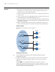
■ Receivers receive VOD information in the multicast mode. Receivers of different
organizations form stub networks N1 and N2, and Host A and Host C are
multicast receivers in N1 and N2 respectively.
■ Switch A in the IPv6 PIM network connects to N1, and Switch B and Switch C
connect to N2.
■ Switch A connects to N1 through VLAN-interface 100, and to other devices in
the IPv6 PIM-DM network through VLAN-interface 101.
■ Switch B and Switch C connect to N2 through their respective VLAN-interface
200, and to other devices in the IPv6 PIM network through VLAN-interface 201
and VLAN-interface 202.
■ MLDv1 is required between Switch A and N1, and between the other two
Switches (Switch B and Switch C) and N2, with Switch B as the MLD querier.
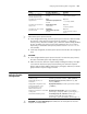
Network diagram
Figure 195 Network diagram for MLD configuration
Configuration procedure
n
In the configuration procedure, only the commands related to the MLD
configuration are listed.
1 Configure IPv6 addresses for the router interfaces and an IPv6 unicast protocol.
Configure an IPv6 address and prefix length for each interface as shown in
Figure 195.
Configure OSPFv3 for interoperation between the switches. Ensure the
network-layer interoperation between Switch A, Switch B, and Switch C on the
IPv6 PIM-DM network and dynamic update of routing information between the
switches through a unicast routing protocol.
Switch A
Switch B
Switch C
Querier
Ethernet Ethernet
N1
N2
Receiver
Receiver
Host A
Host B
Host C
Host D
Vlan-int100
3000::12/64
Vlan-int200
3001::10/64
Vlan-int200
3001::12/64
Vlan-int101
Vlan-int201
Vlan-int202
IPv6 PIM network