
3Com Switch 8800 Advanced Software V5 Configuration Guide

MLD Snooping Configuration Examples 667
Examples 2 (Static
Router Port
Configuration)
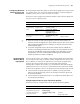
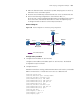
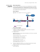
Network requirements
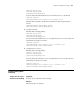
As shown in Figure 199, Router A, which acts as the MLD querier on the subnet,
connects to the IPv6 multicast source through Ethernet1/1/2 and to Switch A (a
Switch 8800) through Ethernet1/1/1. While no IPv6 multicast protocol is running
on Router B, perform the following configuration so that Switch A can forward all
the received IPv6 multicast data to Router B.
Network diagram
Figure 199 Network diagram for static router port configuration
Configuration procedure
1 Configure the IPv6 address of each interface
Configure an IP address and address prefix for each interface. The specific
configuration procedure is omitted here.
2 Configure Router A
# Enable IPv6 multicast routing, enable IPv6 PIM-DM on each interface, and enable
MLDv1 on Ethernet1/1/1.
<RouterA> system-view
[RouterA] multicast ipv6 routing-enable
[RouterA] interface ethernet 1/1/1
[RouterA-Ethernet1/1/1] mld enable
[RouterA-Ethernet1/1/1] mld version 1
[RouterA-Ethernet1/1/1] pim ipv6 dm
[RouterA-Ethernet1/1/1] quit
[RouterA] interface ethernet 1/1/2
[RouterA-Ethernet1/1/2] pim ipv6 dm
[RouterA-Ethernet1/1/2] quit
n
The above configuration on Router A is for reference only. Refer to the specific
situation of your device when performing the configuration.
3 Configure Switch A
# Create VLAN 100.
IPv6 multicast packets
Source
Router A Switch A
Receiver
Host B
Host A
Eth1/1/3
Eth1/1/1
Eth1/1 /2
Router B
Internet
MLD querier
1::1 /64
Eth1 /1/4
Eth1/1/1
2001::1/64
Eth1 /1/2
1::2/64