
3Com Switch 8800 Advanced Software V5 Configuration Guide


IPv6 PIM Configuration Examples 701
exist in each stub network. The entire PIM domain operates in the sparse
mode.
■ Host A and Host C are IPv6 multicast receivers in two stub networks N1 and
N2.
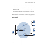
■ Switch A connects to the network where the source resides through
VLAN-interface 100.
■ Switch B connect to N1 through VLAN-interface 200, and to Switch A and
Switch D through VLAN-interface 101 and VLAN-interface 103 respectively.
■ Switch C connects to N2 through VLAN-interface 300 and to Switch D through
VLAN-interface 104.
■ Switch D connects to Switch A, Switch B, and Switch C, and its VLAN-interface
103 acts a C-BSR and a C-RP, with the range of IPv6 multicast groups served by
the C-RP being FF0E::1/64.
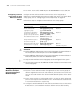
Network diagram
Figure 210 Network diagram for IPv6 PIM-SM configuration
Device Interface IP address Device Interface IP address
Switch A Vlan-int100 2001::1/64 Switch C Vlan-int104 2005::2/64
Vlan-int101 2002::1/64 Vlan-int300 4001::2/64
Vlan-int102 2003::1/64 Vlan-int102 2003::2/64
Switch B Vlan-int101 2002::2/64 Switch D Vlan-int103 3002::2/64
Vlan-int103 2004::1/64 Vlan-int104 2005::1/64
Vlan-int200 3001::1/64
2001::5 /64
Source
Ethernet
Ethernet
Ethernet
IPv6 PIM-SM
Switch B
Switch C
Switch A
Receiver
Host A
Host B
Host C
Host D
Receiver
N1
N2
Switch D
Vlan-int200
Vlan-int300
Vlan-int100
Vlan-int103
Vlan-int103
V
l
a
n
-
i
n
t1
0
1
V
l
a
n
-
i
n
t1
0
1
Vlan-int104
Vlan-int104
Vlan-int102
Vlan-int102