
3Com Switch 8800 Advanced Software V5 Configuration Guide


UDP Helper Configuration Examples 715
UDP Helper
Configuration
Examples
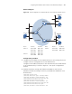
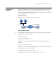
Network requirements
The interface VLAN-interface 1 on the UDP Helper enabled Switch A has the IP
address of 10.110.1.1/16, connecting to the network segment 10.110.0.0/16.
Enable the forwarding of broadcast packets with the UDP destination port number
55 to the destination server 202.38.1.2/24.
Network diagram
Figure 212 Network diagram for UDP Helper configuration
Configuration procedure
n
The following configuration assumes that a route from Switch A to the network
segment 202.38.1.0/24 is available.
# Enable UDP Helper.
<SwitchA> system-view
[SwitchA] udp-helper enable
# Enable the forwarding of broadcast packets with the UDP destination port
number 55.
[SwitchA] udp-helper port 55
# Specify the server with the IP address of 202.38.1.2 as the destination server to
which UDP packets are to be forwarded.
[SwitchA] interface vlan-interface 1
[SwitchA-Vlan-interface1] ip address 10.110.1.1 16
[SwitchA-Vlan-interface1] udp-helper server 202.38.1.2
IP network
Vlan-int1
10.110 .1.1 /16
Vlan-int1
202.38 .1.2/24
Switch A Switch B
Server