
3Com Switch 8800 Advanced Software V5 Configuration Guide


54
VRRP CONFIGURATION
When configuring VRRP, go to these sections for information you are interested in:
■ “Introduction to VRRP” on page 761
■ “Configuring VRRP for IPv4” on page 767
■ “Configuring VRRP for IPv6” on page 771
■ “IPv4-Based VRRP Configuration Example” on page 774
■ “IPv6-Based VRRP Configuration Example” on page 783
■ “Troubleshooting VRRP” on page 791
n
■ The term router and the icon router in this document refer to a router in a
generic sense or a Switch 8800 running routing protocols.
■ At present, the interfaces that VRRP involves can only be VLAN interfaces for
Switch 8800s.
Introduction to VRRP This section covers these topics:
■ “Overview” on page 761
■ “Basic Concepts of VRRP” on page 762
■ “Format of VRRP Packets” on page 764
■ “Principles of VRRP” on page 766
■ “Operation Modes of VRRP (Taking IPv4-Based VRRP for Example)” on page
766
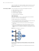
Overview Normally, you can configure a default route to the gateway for every host on a
network, allowing all packets destined to the external networks to be sent over
the default route to the gateway. This enables hosts on a network to communicate
with external networks. However, when the gateway fails, all the hosts using the
gateway as the default next-hop router are isolated from the external network.
Apparently, this approach to enabling hosts on a network to communicate with
external networks is easy to configure but it imposes a very high requirement of
performance stability on the device acting as the gateway. A common way to
improve system reliability is to use more egress gateways, introducing the problem
of routing among the multiple egresses.
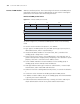
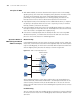
Virtual router redundancy protocol (VRRP) was designed to address this problem.
Deploying VRRP on multicast and broadcast LANs such as Ethernet, you can assure
that the system can still provide highly reliable default links without changing
configurations when a device fails.