
3Com Switch 8800 Advanced Software V5 Configuration Guide


IPv4-Based VRRP Configuration Example 775
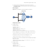
■ If Switch A operates normally, packets sent from Host A to Host B are
forwarded by Switch A; if Switch A fails, packets sent from Host A to Host B are
forwarded by Switch B.
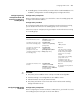
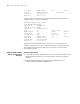
Network diagram
Figure 235 Network diagram for single VRRP standby group configuration
Configuration procedure
1 Configure Switch A
# Configure VLAN 2.
<SysnameA> system-view
[SysnameA] vlan 2
[SysnameA-vlan2] port ethernet 2/1/4
[SysnameA-vlan2] quit
[SysnameA] interface vlan-interface 2
[SysnameA-Vlan-interface2] ip address 202.38.160.1 255.255.255.0
# Create standby group 1 and configure its virtual IP address as 202.38.160.111.
[SysnameA-Vlan-interface2] vrrp vrid 1 virtual-ip 202.38.160.111
# Configure the priority of Switch A in the standby group 1 as 110.
[SysnameA-Vlan-interface2] vrrp vrid 1 priority 110
# Configure Switch A to work in preemption mode and configure the preemption
delay to five seconds.
[SysnameA-Vlan-interface2] vrrp vrid 1 preempt-mode timer delay 5
[SysnameA-Vlan-interface2] return
2 Configure Switch B
# Configure VLAN 2.
<SysnameB> system-view
[SysnameB] vlan 2
[SysnameB-vlan2] port ethernet 2/1/4
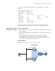
Host A
Switch A
Switch B
Virtual IP address:
202.38.160.111/24
Vlan-int2
202.38.160.1/24
Vlan-int2
202.38.160 .2/24
Host B
202.38.160 .3/24
203.2.3 .1/24
Internet