
3Com Switch 8800 Advanced Software V5 Configuration Guide


IPv4-Based VRRP Configuration Example 777
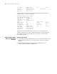
# If Switch A fails, the detailed information of standby group 1 on Switch B is
displayed.
<SysnameB> display vrrp verbose
IPv4 Standby Information:
Run Method : VIRTUAL-MAC
Virtual IP Ping : Enable
Interface : Vlan-interface2
VRID : 1 Adver. Timer : 1
Admin Status : UP State : Master
Config Pri : 100 Run Pri : 100
Preempt Mode : YES Delay Time : 0
Auth Type : NONE
Virtual IP : 202.38.160.111
Virtual MAC : 0000-5e00-0101
Master IP : 202.38.160.2
The above information indicates that if Switch A fails, Switch B becomes the
master, and packets sent from host A to host B are forwarded by Switch B.
VRRP Interface Tracking
Configuration Example
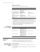
Network requirements
■ Host A needs to access Host B on the Internet, using 202.38.160.111/24 as its
default gateway.
■ Switch A and Switch B belong to standby group 1 with the virtual IP address of
202.38.160.111.
■ If Switch A operates normally, packets sent from Host A to Host B are
forwarded by Switch A; if Switch A is in work, but when its interface
Vlan-interface3 which connects to the internet is not available, packets sent
from Host A to Host B are forwarded by Switch B.
Network diagram
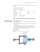
Figure 236 Network diagram for interface tracking in VRRP
Host A
Switch A
Switch B
Virtual IP address:
202.38.160.111/24
Vlan-int2
202.38 .160.1 /24
Vlan-int2
202.38.160.2/24
Host B
202.38 .160.3/24
203.2 .3.1/24
Vlan-int3
Internet