
3Com Switch 8800 Advanced Software V5 Configuration Guide


IPv6-Based VRRP Configuration Example 783
VRID : 2 Adver. Timer : 1
Admin Status : UP State : Master
Config Pri : 110 Run Pri : 110
Preempt Mode : YES Delay Time : 0
Auth Type : NONE
Virtual IP : 202.38.160.112
Virtual MAC : 0000-5e00-0102
Master IP : 202.38.160.2
The above information indicates that in standby group 1 Switch A is the master,
Switch B is the backup and the host with the default gateway of
202.38.160.111/24 accesses the Internet through Switch A; in standby group 2
Switch A is the backup, Switch B is the master and the host with the default
gateway of 202.38.160.112/24 accesses the Internet through Switch B.
IPv6-Based VRRP
Configuration
Example
This section provides these configuration examples:
■ “Single VRRP Standby Group Configuration Example” on page 783
■ “VRRP Interface Tracking Configuration Example” on page 786
■ “Multiple VRRP Standby Group Configuration Example” on page 789
Single VRRP Standby
Group Configuration
Example
Network requirements
■ Host A needs to access Host B on the Internet, using FE80::10 as its default
gateway.
■ Switch A and Switch B belong to standby group 1 with the virtual IPv6 address
of FE80::10.
■ If Switch A operates normally, packets sent from Host A to Host B are
forwarded by Switch A; if Switch A fails, packets sent from Host A to Host B are
forwarded by Switch B.
Network diagram
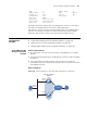
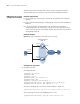
Figure 238 Network diagram for single IPv6 VRRP standby group configuration
Host A
Switch A
Switch B
Virtual IPv6 address:
FE80::10
Vlan-int2
FE80::1
Vlan-int2
FE80::2
Host B
Gateway:
FE80::10
Internet