
3Com Switch 8800 Advanced Software V5 Configuration Guide


786 CHAPTER 54: VRRP CONFIGURATION
The above information indicates that if Switch A fails, Switch B becomes the
master, and packets sent from Host A to Host B are forwarded by Switch B.
VRRP Interface Tracking
Configuration Example
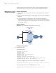
Network requirements
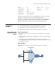
■ Host A needs to access Host B on the Internet, using FE80::10 as its default
gateway.
■ Switch A and Switch B belong to standby group 1 with the virtual IP address of
FE80::10.
■ If Switch A operates normally, packets sent from Host A to Host B are
forwarded by Switch A; if Switch A is in work, but its Vlan-interface3 which
connects to the Internet is not available, packets sent from Host A to Host B are
forwarded by Switch B.
Network diagram
Figure 239 Network diagram for IPv6 VRRP interface tracking
Configuration procedure
1 Configure Switch A
# Configure VLAN 2.
<SysnameA> system-view
[SysnameA] ipv6
[SysnameA] vlan 2
[SysnameA-vlan2] port ethernet 1/5
[SysnameA-vlan2] quit
[SysnameA] interface vlan-interface 2
[SysnameA-Vlan-interface2] ipv6 address fe80::1 link-local
[SysnameA-Vlan-interface2] ipv6 address 1::1 64
# Create a standby group 1 and set its virtual IP address to FE80::10.
[SysnameA-Vlan-interface2] vrrp ipv6 vrid 1 virtual-ip fe80::10 link-local
# Set the priority of Switch A in standby group 1 to 110.
[SysnameA-Vlan-interface2] vrrp ipv6 vrid 1 priority 110
Host A
Switch A
Switch B
Virtual IPv6 address:
FE80::10
Vlan-int2
FE80::1
Vlan-int2
FE80::2
Host B
Gateway:
FE80::10
Vlan-int3
Internet