
3Com Switch 8800 Advanced Software V5 Configuration Guide


IPv6-Based VRRP Configuration Example 789
Admin Status : UP State : Master
Config Pri : 100 Run Pri : 100
Preempt Mode : YES Delay Time : 5
Auth Type : SIMPLE TEXT Key : hello
Virtual IP : FE80::10
Virtual MAC : 0000-5e00-0201
Master IP : FE80::2
The above information indicates that if Vlan-interface3 on Switch A is not
available, the priority of Switch A reduces to 80 and it becomes the backup.
Switch B becomes the master and packets sent from Host A to Host B are
forwarded by Switch B.
Multiple VRRP Standby
Group Configuration
Example
Network requirements
■ In the network, some hosts use FE80::10 as their default gateway and some
hosts use FE80::20 as their default gateway.
■ Load sharing and mutual backup between default gateways can be
implemented by using VRRP standby groups.
Network diagram
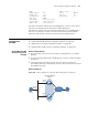
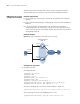
Figure 240 Network diagram for multiple IPv6 VRRP standby group configuration
Configuration procedure
1 Configure Switch A
# Configure VLAN 2.
<SysnameA> system-view
[SysnameA] ipv6
[SysnameA] vlan 2
[SysnameA-vlan2] port ethernet 2/1/6
[SysnameA-vlan2] quit
[SysnameA] interface vlan-interface 2
[SysnameA-Vlan-interface2] ipv6 address fe80::1 link-local
[SysnameA-Vlan-interface2] ipv6 address 1::1 64
Host A
Host B
Host C
Switch A
Switch B
Virtual IPv6 address 1:
FE80::10
Virtual IPv6 address 2:
FE80::20
Vlan-int2
FE80::1
Vlan-int2
FE80 ::2
Gateway:
FE80::10
Gateway:
FE80::20
Gateway:
FE80::20
Internet