
3Com Switch 8800 Advanced Software V5 Configuration Guide


Displaying and Maintaining Graceful Restart 799
Displaying and
Maintaining Graceful
Restart
Graceful Restart
Configuration
Examples
OSPF-based Graceful
Restart Configuration
Examples
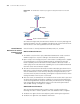
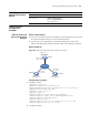
Network requirements
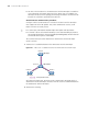
■ Switch A, Switch B and Switch C belong to the same autonomous system and
the same OSPF domain. They are connected through OSPF.
■ Switch A acts as the GR Restarter, and Switch B and Switch C are the GR
Helpers and remain OOB synchronized with Switch A through GR mechanism.
Network diagram
Figure 245 OSPF-based Graceful Restart configuration example
Configuration procedure
1 Configure Switch A.
<SysnameA> system-view
[SysnameA] interface vlan-interface 100
[SysnameA-Vlan-interface100] ip address 192.1.1.1 255.255.255.0
[SysnameA-Vlan-interface100] quit
[SysnameA] router id 1.1.1.1
[SysnameA] ospf 100
[SysnameA-ospf-100] enable link-local-signaling
[SysnameA-ospf-100] enable out-of-band-resynchronization
[SysnameA-ospf-100] graceful-restart
[SysnameA-ospf-100] area 0
[SysnameA-ospf-100-area-0.0.0.0] network 192.1.1.0 0.0.0.255
[SysnameA-ospf-100-area-0.0.0.0] return
2 Configure Switch B.
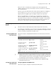
To do... Use the command... Remarks
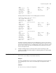
Display the Graceful Restart
state for IS-IS
display isis graceful-restart
status [ level-1 | level-2 ] [
process-id | vpn-instance
vpn-instance-name ]
Available in any view
Vlan-int100
192.1.1.1/24
Vlan-int100
192 .1.3 .1/ 24
Vlan-int100
192.1.2.1/24
GR helper GR helper
GR restarter
Switch A
Switch C
Switch B
Router ID: 1.1 .1.1
Router ID: 2.2 .2.2 Router ID: 3.3.3.3
Network