
3Com Switch 8800 Advanced Software V5 Configuration Guide

Link Aggregation Configuration Example 81
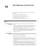
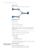
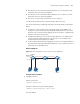
Network diagram
Figure 22 Network diagram for link aggregation
Configuration procedure
n
■ This example only describes how to configure link aggregation on Switch A. To
achieve link aggregation, do the same on Switch B.
■ Manual aggregation group, static aggregation group, and dynamic
aggregation group can all be used here.
1 In manual aggregation approach
# Create manual aggregation group 1.
<SwitchA> system-view
[SwitchA] link-aggregation group 1 mode manual
# Add ports Ethernet 1/1/1 through Ethernet 1/1/3 to the aggregation group.
[SwitchA] interface ethernet 1/1/1
[SwitchA-Ethernet1/1/1] port link-aggregation group 1
[SwitchA-Ethernet1/1/1] quit
[SwitchA] interface ethernet 1/1/2
[SwitchA-Ethernet1/1/2] port link-aggregation group 1
[SwitchA-Ethernet1/1/2] quit
[SwitchA] interface ethernet 1/1/3
[SwitchA-Ethernet1/1/3] port link-aggregation group 1
2 In static aggregation approach
# Create static aggregation group 1.
<SwitchA> system-view
[SwitchA] link-aggregation group 1 mode static
# Add ports Ethernet 1/1/1 through Ethernet 1/1/3 to the aggregation group.
[SwitchA] interface ethernet 1/1/1
[SwitchA-Ethernet1/1/1] port link-aggregation group 1
[SwitchA-Ethernet1/1/1] quit
[SwitchA] interface ethernet 1/1/2
[SwitchA-Ethernet1/1/2] port link-aggregation group 1
[SwitchA-Ethernet1/1/2] quit
[SwitchA] interface ethernet 1/1/3
[SwitchA-Ethernet1/1/3] port link-aggregation group 1
3 In dynamic aggregation approach
Device
A
Link aggregation
Device B