
3Com Switch 8800 Advanced Software V5 Configuration Guide

Port Mirroring Configuration Example 89
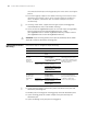
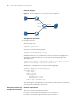
■ Port Ethernet 1/1/3 of Switch A and port Ethernet 1/1/1 of Switch B are two
trunk ports. They are connected together.
■ Port Ethernet 1/1/2 of Switch B and port Ethernet 1/1/1 of Switch C are two
trunk ports. They are connected together.
■ The Server is connected to port Ethernet 1/1/2 of Switch C.
It is desired to monitor packets of Host A and Host B on the Server.
This can be achieved by configuring remote port mirroring groups, as described
below.
■ On Switch A, create a remote source mirroring group; create VLAN 2 and
configure it as the remote port mirroring VLAN; add port Ethernet 1/1/1 and
Ethernet 1/1/2 to the port mirroring group as two source ports. Configure port
Ethernet 1/1/4 as the reflector port.
■ Configure port Ethernet 1/1/3 of Switch A, port Ethernet 1/1/1 and Ethernet
1/1/2 of Switch B, and port Ethernet 1/1/1 of Switch C as trunk ports and
configure them to permit packets of VLAN 2.
■ Create a remote destination mirroring group on Switch C. Configure VLAN 2 as
the remote port mirroring VLAN and port Ethernet 1/1/2, to which the server is
connected, as the destination port.
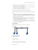
Network diagram
Figure 24 Network diagram for remote port mirroring configuration
Configuration procedure
1 Configure Switch A.
# Enter system view.
<Sysname> system-view
# Create a remote source port mirroring group.
[Sysname] mirroring-group 1 remote-source
# Create VLAN 2.
Switch A
Switch B
Switch C
Eth1/1 /2Eth1/1 /1
Eth1 /1/3 Eth1/1/1
Eth1 /1/2
Eth1/1/1
Eth1 /1/2
Server
Host A Host B
Eth1/1 /4
Reflector Port