
3Com Switch 8800 Advanced Software V5 Configuration Guide


MSTP Overview 95
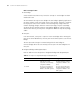
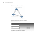
Figure 25 A schematic diagram of designated bridges and designated ports
As shown in Figure 25, AP1 and AP2, BP1 and BP2, and CP1 and CP2 are ports on
Switch A, Switch B, and Switch C.
■ If Switch A forwards configuration BPDUs to Switch B through AP1, the
designated bridge for Switch B is Switch A, and the designated port is AP1 on
Switch A.
■ Two Switches are connected to the LAN: Switch B and Switch C. If Switch B
forwards configuration BPDUs to the LAN, the designated bridge for the LAN is
Switch B, and the designated port is BP2 on Switch B.
n
All the ports on the root bridge are designated ports.
How STP works
STP identifies the network topology by transmitting configuration BPDUs between
network devices.
Configuration BPDUs contain sufficient information for network devices to
complete the spanning tree computing. A configuration BPDU mainly contains the
following information:
■ Root bridge ID, formed by root bridge priority and MAC address
■ Root path cost
■ Designated bridge ID, formed by designated bridge priority and MAC address
■ Designated port ID, formed by designated port priority and port name
■ Message age: age of the configuration BPDU
■ Max age: maximum age of the configuration BPDU
■ Hello time: interval to send configuration BPDUs
■ Forward delay: state transition delay of the port
1 A simplified STP computing model
n
For the convenience of description, the description and examples below involve
only four parts of a configuration BPDU:
■ Root bridge ID (in the form of device priority)
LAN
AP1 AP2
Switch A
Switch B Switch C
BP1
BP2
CP1
CP2