
3Com Switch 8800 Advanced Software V5 Configuration Guide


MSTP Overview 97
The process of selecting the root port and designated ports is as follows:
n
When the network topology is stable, only the root port and designated ports
forward traffic, while other ports are all in the blocked state - they only receive STP
packets but do not forward user traffic.
Once the root bridge, the root port on each non-root bridge and designated ports
have been successfully elected, the entire tree-shaped topology has been
constructed.
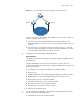
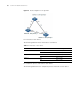
The following is an example of how the STP algorithm works. The specific network
diagram is shown in
Figure 26, where the priority of Switch A is 0, the priority of
Switch B is 1, the priority of Switch C is 2, and the path costs of the links are 5, 10
and 4.
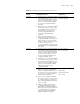
Tab le 10 Selection of the root port and designated ports
Step Description
1 The root port is the port through which the optimum configuration BPDU was
received.
2 Based on the configuration BPDU and the path cost of the root port, the device
generates a designated port configuration BPDU for each of the rest ports as follows:
■ Using the root bridge ID of the configuration BPDU of the root port as the root
bridge ID.
■ Using the sum of the root path cost of the configuration BPDU of the root port
and the path cost corresponding to the root port as the root path cost.
■ Using the local device ID as the designated bridge ID.
■ Using the local port ID as the designated port ID.
3 The device compares the configuration BPDUs generated for its ports with the
configuration BPDUs received on the corresponding port and acts as follows.
■ If the received configuration BPDU is superior, the device will block this port
without changing its configuration BPDU, so that the port only receives
configuration BPDUs, but does not forward packets or send configuration BPDUs.
■ If the generated configuration BPDU is superior, this port will serve as the
designated port, and the device sends the generated configuration BPDU through
the port periodically.