3Com® Switch 8800 Family Installation Guide Switch 8807 Switch 8810 Switch 8814 www.3Com.com Part No. 10015593, Rev.
3Com Corporation 350 Campus Drive Marlborough, MA USA 01752-3064 Copyright © 2006-2007, 3Com Corporation. All rights reserved. No part of this documentation may be reproduced in any form or by any means or used to make any derivative work (such as translation, transformation, or adaptation) without written permission from 3Com Corporation.
CONTENTS ABOUT THIS GUIDE Conventions 5 Related Documentation 6 About this Document 6 1 PRODUCT OVERVIEW Preface 7 General Architecture 10 Fabric Modules 17 System Specifications 24 Software Features 25 2 I/O AND APPLICATION MODULES Overview 29 3C17511 1-port 10GBASE-X (XENPAK) 29 3C17512 2-port 10GBASE-X (XFP) Module 30 3C17513 12-port 1000BASE-X (SFP) Module 31 3C17514 24-port 1000BASE-X (SFP) Module 32 3C17516 24-port 10/100/1000BASE-T Module 33 3C17525 1-port 10GBASE-X Advanced (XENPAK) Module 33 3
Examining Installation Site Installation Tools 52 4 50 SWITCH INSTALLATION Confirming Installation Preparation 53 Installation Flow 53 Mounting the Switch in User-Supplied Cabinet Connecting PGND Wire and Power Cord 59 Installing Cabling Rack 64 Installing Fan Tray 64 Installing PoE Lightning Protection Box 65 Installing I/O modules 66 Connecting Interface Cables 67 Cable Routing Recommendations 70 Cable Management 70 Verifying the Installation 73 5 54 DEBUGGING THE SYSTEM Setting up Configuration Env
ABOUT THIS GUIDE This guide describes the 3Com® Switch 8800 and how to install hardware, configure and boot software, and maintain software and hardware. This guide also provides troubleshooting and support information for your switch. This guide is intended for Qualified Service personnel who are responsible for configuring, using, and managing the switches.
ABOUT THIS GUIDE Table 2 Text Conventions Convention Description Words in italics Italics are used to: Emphasize a point. Denote a new term at the place where it is defined in the text. Identify menu names, menu commands, and software button names. Examples: From the Help menu, select Contents. Click OK. Words in bold Related Documentation Boldface type is used to highlight command names. For example, “Use the display user-interface command to...
1 Preface PRODUCT OVERVIEW The 3Com Switch 8800 Family of Routing Switches (referred to as the Switch 8800 Family) are intelligent, multi-layer modular LAN switches and are ideal for enterprise environments where non-stop availability of critical applications and the highest performance, security, and granular control are required. The Switch 8800 Family delivers high density Gigabit and 10 Gigabit switching in an integrated chassis platform.
CHAPTER 1: PRODUCT OVERVIEW Currently, the Switch 8800 Family include the following models: ■ Switch 8807: This model provides up to 600 Gbps switching capacity. It supports (for example) up to 240 GE ports and 20 x 10GE ports. Figure 1 3Com Switch 8807 (7-Slot Chassis) ■ Switch 8810: This model provides up to 960 Gbps switching capacity. It supports (for example) up to 192 GE ports and 32 x 10GE ports.
Preface ■ Switch 8814: This model provides up to 1.44 Tbps switching capacity. It supports (for example) up to 576 GE ports and 48 x 10GE ports.
CHAPTER 1: PRODUCT OVERVIEW General Architecture Chassis and Slots The Switch 8800 Family use integrated chassis, which can be subdivided into power area, board area, backplane and fan area.
General Architecture 11 Switch 8810 Figure 5 Switch 8810 slots Fan tray I/O Module I/O Module I/O Module I/O Module Fabric Fabric I/O Module I/O Module I/O Module I/O Module AC PSU PoE Entry AC PSU ■ The Switch 8810 chassis provides ten slots in its board area: The middle two accommodate fabric modules, which can operate in 1+1 redundancy mode; the remaining eight accommodate I/O or application modules, which you can select from various available models. All modules in this area are hot-swappable.
CHAPTER 1: PRODUCT OVERVIEW Switch 8814 Figure 6 Switch 8814 slots Backplane PoE entry Fan tray 2 AC PSU Fan tray 1 I/O Module I/O Module I/O Module I/O Module I/O Module I/O Module Fabric Fabric I/O Module I/O Module I/O Module I/O Module I/O Module I/O Module AC PSU ■ The Switch 8814 chassis provides 14 slots in its board area: The middle two accommodate fabric modules, which can operate in 1+1 redundancy mode; the remaining 12 accommodate I/O or application modules, which you can select from
General Architecture 13 The Switch 8807 uses a passive backplane, which provides five I/O module interfaces, two fabric interfaces, one fan interface, and three -48V power interfaces (two for PSUs and one for PoE entry module). ■ Switch 8810 The Switch 8810 uses a passive backplane, which provides eight I/O module interfaces, two fabric interfaces, one fan interface, and three -48V power interfaces (two for PSUs and one for PoE entry module).
CHAPTER 1: PRODUCT OVERVIEW ■ A Switch 8800 supports up to 4500 W (220 V)/2250 W (110 V) power to its PDs. It determines whether to deliver power to a newly detected PD depending on the power it currently supplied. PoE entry area The PoE-supported Switch 8807/Switch 8810/Switch 8814 chassis has a PoE entry area between the two power supply units.
General Architecture 15 Table 2 describes typical equipment configurations and specifications of external PoE power system. Table 2 Typical equipment configurations and specifications of external PoE power system Item Description Physical dimensions (H x W x D) 177 x 486 x 320.5 mm (7.0 x 19.1 x 12.6 in.
CHAPTER 1: PRODUCT OVERVIEW Role and function The MBUS system is powered by 5 V from the MBUS on the fabric. The 5 V power on the two fabrics are redundant to each other. Each MBUS module is attached to the MBUS, which contains two control lines: MBUS0 and MBUS1. Each card has an independent MBUS module, those on the fabrics are primary MBUS modules, and those on application modules are secondary MBUS modules.
Fabric Modules 17 Table 4 LEDs on fan tray panel Fabric Modules LED Color Status Status RUN Green OFF The fan tray is faulty. ON The fan tray is operating normally. ALM Red OFF The fan tray is operating normally. ON The fan tray is faulty. The Switch Fabric serves as the core of the Switch 8800 Family.
CHAPTER 1: PRODUCT OVERVIEW Figure 10 360 Gbps Switch Fabric panel Compact Flash (CF slot) The 360 Gbps Switch Fabric module provides a CF slot to accommodate a standard CF card, where you can save logging information, host version information, alarming and other diagnostic information and conveniently upgrade software online. The fabric ships with a CF memory card. Management Ports The Management 10Base-T/100Base-TX port uses an RJ-45 connector.
Fabric Modules 19 Table 8 RS232/485 port specifications Item Description Service The port for monitoring and communication with the external subsystem, such as external PoE power supply module ■ Console port The Console port uses an RJ-45 connector. It can be connected to a background terminal for system debugging, maintenance, management, and host software loading.
CHAPTER 1: PRODUCT OVERVIEW Table 11 CF status LED LED Status CFS ON The CF card is in position and is idle. You cannot remove the card. Blinking The CF card is in position and reading/writing data. You cannot remove the card. OFF The CF card is out of position or offline (you can force the in-position CF card to go offline using the appropriate background command). You can remove/insert the card.
Fabric Modules 720 Gbps Switch Fabric 21 Technical specifications This model applies to the 3C17539. See Table 5 for its specifications. Table 14 720 Gbps Switch Fabric specifications Item Specifications CPU MPC755 Boot ROM 512 KB SDRAM 512 MB (expandable to 1 GB) Physical dimensions (W x D) 366.7 x 340 mm (14.4 x 13.4 in.
CHAPTER 1: PRODUCT OVERVIEW Table 15 Management 10Base-T/100Base-TX port specifications Item Description Max. transmission segment over the selected medium 100 m (328 ft.) over the category-5 twisted pair cable (crossover cable is required). Service System program upgrade and network management The following table describes the status LEDs for the management 10Base-T/100Base-TX port. Table 16 Status LEDs for the management 10Base-T/100Base-TX port LED Status LINK OFF No link is present.
Fabric Modules 23 The AUX port uses an RJ-45 connector. The port can serve as a backup port for the Console port to connect a background terminal, or directly connect a modem device, for remote system debugging, configuration, maintenance and management. Table 19 AUX port specifications Item Description Connector RJ-45 Standard Asynchronous EIA/TIA-232 Service Connects a serial port of a PC (through a Modem pair for a remote PC) and runs terminal emulation on the PC.
CHAPTER 1: PRODUCT OVERVIEW You can learn the operating status of 720 Gbps Switch Fabric module by reading the SFS, ACT, ALM and RUN LEDs on it. The following table gives a summary of the four LEDs. Table 22 Status LEDs for the 720 Gbps Switch Fabric module 360 Gbps Switch Fabric LED Status SFS ON The switching fabric unit is active. OFF The switching fabric unit is standby. Green The 720 Gbps Switch Fabric module is faulty. OFF The 720 Gbps Switch Fabric module is faulty.
Software Features 25 Table 23 Technical specifications of the Switch 8800 Family Item Switch 8807 Switch 8810 Switch 8814 fabric module type 360 Gbps Fabric 360 Gbps Switch Fabric 360 Gbps Switch Fabric 720 Gbps Switch Fabric 720 Gbps Switch Fabric Number of I/O module slots 5 8 User interface 10/100/1000BASE-TX RJ45 12 1000BASE-X (SFP) 10BASE-X (XENPAK) 10BASE-X (XFP) Operating temperature 0 to 40C (32 to 104F) Operating humidity (noncondensing) 10% to 90% Storage temperature -10 to 70
CHAPTER 1: PRODUCT OVERVIEW Table 24 Software features of the Switch 8800 Family Item Description Flow control IEEE 802.
Software Features 27 Table 24 Software features of the Switch 8800 Family Item Description Security Hierarchical user management and password protection Password control 802.1x authentication Packet filtering Port-based broadcast frame suppression, speed calculation in bytes or packets Protection from attacks by virus packets, such as DOS attacks AAA/RADIUS/HWTACACS SSH 2.
CHAPTER 1: PRODUCT OVERVIEW
I/O AND APPLICATION MODULES 2 Overview The Switch 8800 Family are modular switches that are designed following industry standards.
CHAPTER 2: I/O AND APPLICATION MODULES Table 26 3C17511 module specifications Panel and LEDs Item Specification Boot ROM 512 KB SDRAM 128 MB/256 MB Physical dimensions (W x D) 366.7 x 340 mm(14.4 x 13.4 in.) Max power consumption 45 W Number of ports One Connector XENPAK/SC Rate 10 Gbps Figure 12 3C17511 module panel The 3C17511 module has two port LEDs for the 10GE port on its panel. Table 27 Port LEDs on the 3C17511 module LED Status Meaning LINK OFF No link is present.
3C17513 12-port 1000BASE-X (SFP) Module 31 Table 28 3C17512 module specifications Panel and LEDs Item Specification Rate 10 Gbps Figure 13 3C17512 module panel The 3C17512 module has two LEDs for each optical port on its panel. Table 29 1000 Mbps optical port LEDs on the 3C17512 module LED Status Meaning LINK OFF No link is present. Green A link is present. OFF No packets are transmitted/received on the port. Orange blinking Packets are being transmitted/received on the port.
CHAPTER 2: I/O AND APPLICATION MODULES The 3C17513 module has two LEDs for each port on its panel. Table 31 Port LEDs on the 3C17513 module LED Status Meaning LINK OFF No link is present. Green A link is present. OFF No packets are transmitted/received on the port. Orange blinking Packets are being transmitted/received on the port.
3C17516 24-port 10/100/1000BASE-T Module Matching Cable 3C17516 24-port 10/100/1000BASE-T Module Specifications 33 You can select appropriate SFP optical modules for the 1000 Mbps SFP optical ports on the 3C17514 module according to your needs. For description of SFP optical modules available to the SFP optical ports and their matching cable types, see Table 66 on page 46. This section provides specifications for the 24-port 10/100/1000BASE-T module (3C17516).
CHAPTER 2: I/O AND APPLICATION MODULES Table 36 3C17511 module specifications Panel and LEDs Item Specification CPU MPC8245 Boot ROM 512 KB SDRAM 128 MB/256 MB Physical dimensions (W x D) 366.7 x 340 mm(14.4 x 13.4 in.) Max power consumption 45 W Number of ports One Connector XENPAK/SC Rate 10 Gbps Figure 17 3C17525 module panel The 3C17525 module has two port LEDs for the 10GE port on its panel.
3C17527 2-port 10GBASE-X (XFP) Advanced Module 35 Table 38 3C17526 module specifications Panel and LEDs Item Specification Connector XFP Rate 10 Gbps Figure 18 3C17526 module panel The 3C17526 module has two LEDs for each optical port on its panel. Table 39 1000 Mbps optical port LEDs on the 3C17526 module LED Status Meaning LINK OFF No link is present. Green A link is present. OFF No packets are transmitted/received on the port.
CHAPTER 2: I/O AND APPLICATION MODULES The 3C17527 module has two LEDs for each optical port on its panel. Table 41 1000 Mbps optical port LEDs on the 3C17527 module LED Status Meaning LINK OFF No link is present. Green A link is present. OFF No packets are transmitted/received on the port. Orange blinking Packets are being transmitted/received on the port.
3C17530 24-port 1000BASE-X (SFP) Advanced Module 3C17530 24-port 1000BASE-X (SFP) Advanced Module Specifications 37 This section provides specifications for the 24-port 1000BASE-X (SFP) Advanced module (3C17530). The 3C17530 Advanced Module provide 24 1000BASE-X (SFP) ports. Table 44 3C17530 module specifications Panel and LEDs Item Specification CPU MPC8245 Boot ROM 512 KB SDRAM 128 MB/256 MB Physical dimensions (W x D) 366.7 x 340 mm (14.4 x 13.4 in.
CHAPTER 2: I/O AND APPLICATION MODULES Table 46 3C17531 module specifications Panel and LEDs Item Specification Boot ROM 512 KB SDRAM 128 MB/256 MB Physical dimensions (W x D) 366.7 x 340 mm (14.4 x 13.4 in.) Max power consumption 110 W Number of ports 24 Connector RJ-45 Rate 10/100/1000 Mbps Figure 22 3C17531 module panel The 3C17531 module has one LED for each port on its panel.
3C17533 24-port 1000BASE-X (SFP) IPv6 Module Panel and LEDs 39 Figure 23 3C17532 module panel The 3C17532 module has one LED for each port on their panel. Table 49 1000 Mbps electrical port LEDs on the 3C17532 module 3C17533 24-port 1000BASE-X (SFP) IPv6 Module Specifications LED Status Meaning LINK/ACT ON A link is present. OFF No link is present. Blinking Packets are being transmitted/received on the port.
CHAPTER 2: I/O AND APPLICATION MODULES Matching Cable 3C17534 24-port 10/100/1000BASE-T IPv6 Module Specifications You can select appropriate SFP optical modules for the 1000 Mbps SFP optical ports on the 3C17533 module according to your needs. For a description of SFP the optical modules available for the SFP optical ports and their matching cable types, see Table 66 on page 46. This section provides specifications for the 24-port 10/100/1000BASE-T IPv6 module (3C17534).
3C17537 2-port 10GBASE-X (XFP) IPv6 Module 41 Table 54 3C17536 module specifications Panel and LEDs Item Specification Boot ROM 512 KB SDRAM 128 MB/256 MB Physical dimensions (W x D) 366.7 x 340 mm (14.4 x 13.4 in.) Number of ports Four Max power consumption (with bottom plate) 160 W Connector XFP Rate 10 Gbps Figure 26 3C17536 module panel The 3C17536 module has two LEDs for each optical port on its panel.
CHAPTER 2: I/O AND APPLICATION MODULES Panel and LEDs Figure 27 3C17537 module panel The 3C17537 module has two LEDs for each optical port on its panel. Table 57 1000 Mbps optical port LEDs on the 3C17537 module LED Status Meaning LINK OFF No link is present. Green A link is present. OFF No packets are transmitted/received on the port. Orange blinking Packets are being transmitted/received on the port.
Application Modules 43 Table 59 Port LEDs on the 3C17538 module Matching Cable Application Modules LED Status Meaning LINK/ACT Solid on A link is present. Solid off No link is present. Blinking The port is transmitting or receiving data. You can select appropriate SFP optical modules for the 1000 Mbps SFP/LC optical ports on the 3C17538 module accordingly to your needs. See Table 66 on page 46 for the available SFP optical modules and their matching cable types.
CHAPTER 2: I/O AND APPLICATION MODULES 3C17546 Firewall Application Module Technical specifications The 3C17546 Firewall Application Module provides eight Gigabit SFP/LC optical ports. Table 61 Technical specifications for the 3C17546 Item Specifications CPU BCM1250 Boot ROM 512 KB SDRAM 1 Gbps Physical dimensions (W x D) 366.7 x 340 mm (14.4 x 13.4 in.
Application Modules 45 Table 63 Technical specifications for the 3CR1754766 Item Specifications SDRAM 512 MB Physical dimensions (W x D) 366.7 x 340 mm (14.4 x 13.4 in.) Front panel Figure 31 Front panel of the 3CR1754766 The 3CR1754766 provides eight 1000Base-X ports, one Console port, one AUX port, three 10/100Base-TX ports and four status LEDs (ATTACK, ACT, ALM and RUN) from left to right on the front panel.
CHAPTER 2: I/O AND APPLICATION MODULES Front panel Figure 32 Front panel of the 3C17548 Transceivers Table 66 documents the 3Com Switch 8800 Family transceivers. Table 66 Transceiver Specifications Optical Power Range (dBm) 3Com Transceiver Name Model Core Size Bandwidth Transmission (microns) (MHz - Km) Range Ordering Number Cable Type Wavelength (nm) Output Input 3Com 10GBASE-LR XENPAK 3CXENPAK92 SMF 9 – 2 m – 10 km (6.6 ft – 6 mi) 1,300 -8.2 to 0.5 -14.4 to 0.
Switch 8800 Port Densities Switch 8800 Port Densities 47 Table 67 describes the modules that are available for the Switch 8800, their maximum port densities, and whether or not the module supports MPLS or IPv6.
CHAPTER 2: I/O AND APPLICATION MODULES
INSTALLATION PREPARATION 3 Safety Recommendations To avoid possible bodily injury and device impairment, please read the following safety recommendations carefully before installing the Switch 8800 Family. The recommendations do not cover every possible hazardous condition. General Safety Recommendations Safety Recommendations against Electricity Safety Recommendations in Moving the Switch 8800 Family c ■ The Switch 8800 Family use redundant PSUs.
CHAPTER 3: INSTALLATION PREPARATION Wearing an ESD-Preventive Wrist Strap To prevent the electronic components from being damaged by the electrostatic discharge (ESD), take ESD measures for the area where the switch is located and note the issues below: ■ Always wear an ESD-preventive wrist strap when installing the parts, especially the electric printed circuit boards. ■ Hold the circuit board by the edge. Do not touch the components or the electric printed circuit.
Examining Installation Site Cleanness Requirements 51 Dust is a hazard to the operating safety of the switch. The indoor dust accumulated on the chassis can cause electrostatic absorption, which may result in the poor contact of the connector or metal contact point. This happens more frequently when indoor relative humidity is low, which will not only shorten the service life of the switch, but also cause communication failure.
CHAPTER 3: INSTALLATION PREPARATION Power Supply Requirements The Switch 8800 Family adopts redundant PSUs for AC PSU: Rated voltage: 100 VAC to 240 VAC, 50 Hz or 60 Hz Maximum tolerance: 90 VAC to 264 VAC, 50 Hz or 60 Hz Maximum power output: 1200 W (Switch 8807)/2000 W (Switch 8810/Switch 8814) Space Requirements Cabinet-Mounting Requirements Installation Tools For the sake of adequate ventilation and easy equipment maintenance, you are recommended to keep one meter of clearance between the rear
4 SWITCH INSTALLATION The Switch 8800 Family shall be installed indoors in a fixed place. Confirming Installation Preparation ■ Make sure that you have read Chapter 3 Installation Preparation carefully. ■ All requirements mentioned in Chapter 3 Installation Preparation have been met.
CHAPTER 4: SWITCH INSTALLATION Mounting the Switch in User-Supplied Cabinet Cabinet Configuration Guideline c CAUTION: ■ Even if no PoE external power supply is installed, it is recommended that you reserve the PoE power supply slot (just cover a 4 U blank filler panel) in the cabinet for later PoE expansion. ■ For components of 4 U or higher, such as chassis and PoE power supply, more screws are required to secure the slide rails in the cabinet considering their weight.
Mounting the Switch in User-Supplied Cabinet 55 Figure 34 One Switch 8807 chassis in a cabinet Switch 8807 11U (1) Blank filler panel (2) Cabling frame (3) Backward cabling frame (4) Reserved for external PoE power supply Guideline: The space marked in Figure 34 must be reserved, and the remaining is at your disposal.
CHAPTER 4: SWITCH INSTALLATION Figure 35 Two Switch 8807 chassis in a cabinet Switch 8807 11U Switch 8807 11U (1) Blank filler panel (2) Cabling frame (3) Backward cabling frame (4) Reserved for external PoE power supply Guideline: The space marked in Figure 35 must be reserved, and the remaining is at your disposal.
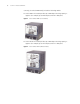
Mounting the Switch in User-Supplied Cabinet 57 Figure 36 One Switch 8810 chassis in a cabinet Switch 8810 14U (1) Blank filler panel (2) Cabling frame (3) Backward cabling frame (4) Reserved for external PoE power supply Guideline: The space marked in Figure 36 must be reserved, and the remaining is at your disposal.
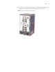
CHAPTER 4: SWITCH INSTALLATION Figure 37 One Switch 8814 chassis in a cabinet Switch 8814 17U (1) Blank filler panel (2) Cabling frame (3) Backward cabling frame (4) Reserved for external PoE power supply Guideline: The space marked in Figure 37 must be reserved, and the remaining is at your disposal. Mounting the Switch in the Cabinet Take the following steps to install the Switch 8800 Family in a 19-inch cabinet.
Connecting PGND Wire and Power Cord 59 Step 6: Align the mounting ears with the square holes in the posts of the cabinet, and fasten the screws in the holes to fix the switch in the cabinet. Connecting PGND Wire and Power Cord Connecting PGND Wire c CAUTION: For the safety of operators and equipment, the switch must be well grounded. The resistance reading between switch chassis and the ground must be less than 1 ohm.
CHAPTER 4: SWITCH INSTALLATION Figure 38 Ground the switch when ground bar is available ˄ 5˅ ˄ 1˅ ˄ 2˅ ˄ 3˅ ˄4 ˅ (1) Air filter (2) Grounding screw (3) PGND wire (4) Ground bar of the equipment room (5) Rear panel of the switch ■ If there is no ground bar but earth nearby and the grounding body is allowed to be buried, you can simply hammer an angle iron or steel pipe no shorter than 0.5 m into the earth.
Connecting PGND Wire and Power Cord 61 power supply has been well grounded at the power distribution room or AC power supply transformer side. Figure 40 Ground the switch via AC PE wire (7) (6) (5) (1) (2) (3) (4) (1) Live line (2) Neutral line (3) PE line (4) 3-core AC input cable (5) Transformer (6) AC power input (7) Front panel of the switch Connecting AC Power Cord c CAUTION: ■ For lightning protection, the AC power should be led through an external lightning device into the switch.
CHAPTER 4: SWITCH INSTALLATION Figure 41 Connect AC power cord to the Switch 8807 (5) (1) Connector-retention clamp (2) Input LED (3) Output LED (4) Fail LED (5) Power switch Figure 42 Connect AC power cord to the Switch 8810/Switch 8814 (1) (2) (3) (4) (5) (1) Connector-retention clamp (2) Input LED (3) Output LED (4) Fail LED (5) Power switch
Connecting PGND Wire and Power Cord Connecting PoE Power Cord n 63 The Switch 8807/Switch 8810/Switch 8814 uses PSE4500-A external PoE power supply, which is connected to the switch through the PoE module at the front bottom of the switch to provide power to PDs (powered devices) under the switch. This section only focuses on the cable connection between the external PoE power supply and the Switch 8800 Family switch.
CHAPTER 4: SWITCH INSTALLATION Figure 44 Front panel of external PoE Power Rack (3C17509) Installing Cabling Rack (1) DC output terminal: NEG(-) (2) DC output terminal: RTN(+) (3) AC input switch (4) AC input socket For your convenience, cabling racks are shipped with the Switch 8800 Family. Take the following steps to install the rack.
Installing PoE Lightning Protection Box c 65 CAUTION: In case of bodily injuries, do not touch any naked wire, terminal or other parts of the product with hazardous voltage labels. Step 1: Wear the ESD-preventive wrist strap, making sure that it makes good skin contact; take the fan tray out from the packing bag.
CHAPTER 4: SWITCH INSTALLATION at the front panel, and then slide it smoothly along the guide rail to the slot, until it fits into the chassis, with its plug fully touching the socket inside the chassis. See Figure 47. Figure 47 Install PoE lightning protection box 3 Fasten the screw on top of the PoE lightning protection box. n Installing I/O modules Generally, the PoE lightning protection box is shipped with the chassis of the switch you ordered. So you need not to install the box.
Connecting Interface Cables 67 Connecting Interface Cables Connecting Console Cable Introduction Console cable is an 8-core shielded cable. At one end of the cable is a crimped RJ-45 connector that is to be plugged into the console port of the switch. At the other end of the cable are a DB-9 (female) connector and a DB-25 (female) connector. You can plug either of them into the 25-pin (male) or 9-pin (male) serial port on the console terminal as needed. The following figure illustrates the console cable.
CHAPTER 4: SWITCH INSTALLATION n The PC serial port is not hot-swappable, so you are not allowed to insert or remove the console cable into or from the PC serial port. When connecting the console cable, first connect the DB9/DB25 end to the PC serial port and then the RJ45 end to the console port of the switch. And removing the console cable is just in inverse order. When removing the console cable, first remove the RJ-45 end and then the DB9/DB25 end.
Connecting Interface Cables 69 Table 72 AUX cable pinouts RJ-45 Signal Direction DB-25 DB-9 8 CTS ← 5 8 Connecting AUX cable Step 1: Plug the RJ-45 connector of the AUX cable into the AUX port of the switch. Step 2: Plug the DB-25 (male) or DB-9 (male) connector at the other end into the serial port of the analog modem.
CHAPTER 4: SWITCH INSTALLATION Figure 51 LC connector Connecting fiber Step 1: Plug one end of the fiber into the SFP optical module of the Switch 8800 Family. Step 2: Connect the other end of the fiber into the corresponding device. c CAUTION: When the optical interface has not been connected with a fiber connector or its dust-proof mesh is open, there might be some invisible radiation emitted from the optical interface. So do not look into the optical interface directly.
Cable Management 71 Figure 52 Cable bundling example I Intertwined Bent ■ The bending radius of cable body cannot be less than twice of the cable diameter. The bending radius of the cable cannot be less than 5 times of its diameter at the place where it is led out of the connector; ■ Different cables (power cord, signal cable, PGND wire, etc.) should be cabled and bundled separately rather than together in the cabinet. If they are close to each other, you can cable them in cross-shape.
CHAPTER 4: SWITCH INSTALLATION ■ Bundle the cables wherever cable bending cannot be avoided. However, the cable ties cannot be placed inside the bending area in case of the likelihood of cable core break due to excessive stress. See the following figure. Figure 54 Cable bundling example III ■ The spare cables or excessive cable parts should be folded and bundled and placed at a right place in the cabinet or on the cabling channel.
Verifying the Installation 73 ■ When using a hard power cord, fix it near its terminal so as to free the terminal and the cable from stress; ■ Do not use tapping screws to fasten the connecting terminals; ■ The power cords of the same type and in the same direction should be bundled together and kept neatly and straight; The following table lists the requirements in the bundling with cable ties.
CHAPTER 4: SWITCH INSTALLATION
5 Setting up Configuration Environment DEBUGGING THE SYSTEM Connect a terminal (a PC in Figure 56) to the switch with a console cable. Figure 56 Networking environment for switch configuration Switch To the console port To the serial port Console cable PC Connecting the Cables 1 Insert the DB-9 (or DB-25) female connector of the Console cable into the serial port on the PC (the Console terminal). 2 Insert the RJ-45 connector of the cable into the Console port on the switch.
CHAPTER 5: DEBUGGING THE SYSTEM You must set the baud rate to 9600, data bits to 8, no parity check, stop bit to 1, and flow control to none, and select VT100 for terminal emulation. Specifically, 1 Click Start→Programs→Accessories→Communications→HyperTerminal to access the Hyper Terminal window. The Connection Description dialog box displays. 2 Click the red phone icon in the window to set up a new connection. 3 Enter the name of the new connection in the Name field and OK.
Powering and Booting the Switch ■ Boot Interface 77 All the system LEDs on the fabrics function normal. The Switch 8807 is used as an example in this section. The following is the information that will be output at the Console terminal when you power on the switch. ZBB_TEST Starting...
CHAPTER 5: DEBUGGING THE SYSTEM
6 SWITCH MONITORING AND MAINTENANCE Monitoring the Switch Although the Switch 8800 Family has undergone a comprehensive factory test before delivery, an improper installation may cause problems. This chapter describes how to troubleshoot the Switch 8800 Family. Troubleshooting Console Terminal If the system running properly, when you power on the switch, you will see the boot information on the console terminal.
CHAPTER 6: SWITCH MONITORING AND MAINTENANCE The following PSU faults may appear on the switch. Follow the instructions provided to resolve the problem. Display Power Command Indicates the PSU is Not in Position The Input LED (green) and Output LED (green) stay ON, but the display power command shows that the PSU is not in position (but the other PSU operates normally). This problem is likely caused by a poor connection (badly seated) between the PSU and the backplane.
Hardware Maintenance Troubleshooting I/O Module ■ The fans are working normally. ■ The rotation of the fans has not been blocked. ■ The blank filler panels have been inserted into the I/O module slots. 81 The Switch 8800 Family provides I/O moduleX LEDs on the fabric so that you can check the state of these I/O modules. Table 77 I/O Module LEDs Indicator State description RUN ON indicates an I/O module failure. OFF indicates that the I/O module has failed or it is not in position at all.
CHAPTER 6: SWITCH MONITORING AND MAINTENANCE 4 Hold the handle of the PSU and pull the PSU gently out of the chassis along the guides. Figure 57 Remove and install the AC PSU Installing an AC PSU 1 Hold the handle of the PSU with one hand and the bottom of the PSU with another hand, and gently slide the PSU into the chassis along the guides until it is secure in the backplane. 2 Fasten the screws at both sides of the PSU panel with a flathead screwdriver.
Hardware Maintenance 83 Figure 58 Remove the air filter of AC PSU (1) PSU (2) Air filter (3) Air filter cover Installing the air filter of PSU To install the PCU’s air filter: 1 Ensure that the black mesh is contained within the air filter cover. Figure 59 Installing the PSU Air Filter 2 Hold the air filter cover by the upper and lower edges with your index finger and thumb and push it inside the PSU.
CHAPTER 6: SWITCH MONITORING AND MAINTENANCE Removing and Cleaning the Chassis’s Air Filter 1 Unscrew the screws at the top and bottom of the air filter with a flathead screwdriver. 2 Hold the air filter at the left-rear by its upper and lower edges, pull part of it out of the chassis, put one hand underneath the air filter to hold it, and pull it out slowly along the guides.
Hardware Maintenance 85 Installing a Module 1 Wear the ESD-preventive wrist strap and unscrew the mounting screws fixing the blank filter panel in the slot where you want to install the module, and remove the blank filler panel. 2 Hold the ejector levers of the card with both hands and pull them outward, align the card with the guides in the chassis, and slide it gently into the slot until its positioning pin touches the positioning hole in the chassis.
CHAPTER 6: SWITCH MONITORING AND MAINTENANCE Upgrading the Software Required cables This section describes how to updated the software on the Switch 8800. ■ Console cable (for serial interface) ■ One crossover and one standard network cables ■ Debug cable (for serial interface) To upgrade the software: 1 Confirm that the host program is loaded before initiating the software upgrade. 2 Check the current version of the host and Boot ROM programs.
Upgrading the Software 87 Board self testing........................... The board is steady SlotNo of this board is 6 The MCX is exist BootRom main system CRC check is OK 82559 register testing is OK EPLD1 testing is OK EPLD2 testing is OK 16c2552 register testing is OK Please check LEDs......................LED testing finished The switch Mac address is 00e0.fc00.1111 Press Ctrl+B to enter Boot Menu... 5 Password : 1 Press as prompted to display the system Password : prompt.
CHAPTER 6: SWITCH MONITORING AND MAINTENANCE Figure 62 Hyper Terminal serial interface attribute settings Upgrading software through console port (XModem) XModem is a file transfer protocol used for its simplicity and performance. It transmits files through serial interfaces, supporting 128 bytes and 1Kbytes in data units, checksum and CRC checking modes, and multiple transmissions attempts (usually 10 attempts) when packet errors are found.
Upgrading the Software 89 2 Type 4 in the serial interface submenu and press Enter to set the serial interface download parameters from the following menu: 1: 9600(default) 2: 19200 3: 38400 4: 57600 5: 115200 please select an appropriate baudrate: Enter your choice(1-5): 5 3 Select the download speed as needed. For example, enter 5 to select the download speed of 115200 bps, then press Enter. The system displays the following information: BaudRate is 115200 bps.
CHAPTER 6: SWITCH MONITORING AND MAINTENANCE Figure 63 Send File dialog box 8 Click Send. The Xmodem dialog box displays. 9 After downloading the program successfully, the system begins to write the data into the Flash memory. When the download is finished, the serial interface displays the following submenu again. XMODEM downloading ...CCC download successfully! flash:/ s8500.
Upgrading the Software 91 4 Enter 5 at Boot menu prompt and press Enter. The system displays the download application program menu: ETHERNET SUBMENU 1. Download file to SDRAM through ethernet interface and boot 2. Download file to Flash through ethernet interface 3. Download file to HardDisk through ethernet interface 4. Modify ethernet interface boot parameter 0.
CHAPTER 6: SWITCH MONITORING AND MAINTENANCE inet on ethernet (e) : 1.1.1.1 host inet (h) : 1.1.1.2 flags (f) : 0x80 Prepare for loading....OK Loading......done flash:/s8500.
Upgrading the Software 93 0. Reboot Enter your choice(0-7): Enter your choice(0-7): 6 Please input ’0’ or ’1’ (’0’:Boot from Flash, ’1’:Boot from CF card) BootDev = 0 FlashFileName = Switch 8800 Family-Comware 310-R1212.app Upgrading the Software Using the CLI If your terminal is connected to the switch over a network, you can load the Boot ROM and host programs remotely through the CLI using FTP.
CHAPTER 6: SWITCH MONITORING AND MAINTENANCE c CAUTION: ■ You must reboot the switch using the reboot command to validate the host program. If Flash memory space is not enough, you can delete some of the program files in Flash after completing the Boot ROM loading. (3Com recommends that you delete the host program that is no longer in use.) Then upload the host program to the switch using FTP. ■ Make sure that you have saved other the configuration before rebooting.
Password Loss ■ 95 Check that the host program exists and that the current host program is running. Insufficient Flash memory Password Loss ■ Empty the recycle bin when the I/O module starts. ■ Delete the unused files in the Flash. If the switch’s Super password or Boot ROM password, contact your local support representative.
CHAPTER 6: SWITCH MONITORING AND MAINTENANCE
LIGHTNING PROTECTION OF THE SWITCH A Installing a Lightning Arrester for the AC Power c This appendix describes how to install the lightning arrester for the AC power (a socket strip with lightning protection) CAUTION: A lightning arrester is not shipped with the switch. You must purchase it separately, if needed.
CHAPTER A: LIGHTNING PROTECTION OF THE SWITCH connected in right direction. When the red LED is on, use a multimeter to examine the polarity at the arrester’s power socket. If it is same as that of the power socket in the equipment room, it means that the arrester is not well grounded. If it is adverse to that of the power socket in the equipment room, it means that the arrester’s power socket is set to the reverse polarity.
Installing a Lightning Arrester for the Network Port 99 Figure 65 Installation diagram of a network port’s lightning arrester Network cable indoors Network cable from outdoors Switch Lightning arrester for the network port (attached onto the chassis) Lightning arrester ground wire Power input Switch grounding screw Metal cabinet that contains the switch Installation precautions To ensure that the network port’s lightning arrester does not affect performance, make sure that the lightning arrester for
CHAPTER A: LIGHTNING PROTECTION OF THE SWITCH
B 3COM NETWORK MANAGEMENT 3Com has a range of network management applications to address networks of all sizes and complexity, from small and medium businesses through large enterprises. The applications include: ■ 3Com Network Supervisor ■ 3Com Network Director ■ 3Com Network Access Manager ■ 3Com Enterprise Management Suite ■ Integration Kit with HP OpenView Network Node Manager Details of these and other 3Com Network Management Solutions can be found at www.3com.
APPENDIX B: 3COM NETWORK MANAGEMENT 3Com Network Director 3Com Network Director (3ND) is a standalone application that allows you to carry out key management and administrative tasks on midsized networks. By using 3ND you can discover, map, and monitor all your 3Com devices on the network. It simplifies tasks such as backup and restore for 3Com device configurations as well as firmware and agent upgrades.
3Com Enterprise Management Suite 3Com Enterprise Management Suite 103 3Com Enterprise Management Suite (EMS) delivers comprehensive management that is flexible and scalable enough to meet the needs of the largest enterprises and advanced networks.
APPENDIX B: 3COM NETWORK MANAGEMENT