Installation and Getting Started Guide ProCurve Series 2600 Switches PoE Power over Ethernet Devices www.procurve.
ProCurve Series 2600 Switches Installation and Getting Started Guide
© Copyright 2001, 2005, 2008 Hewlett-Packard Development Company, L.P. The information contained herein is subject to change without notice. This document contains proprietary information, which is protected by copyright. No part of this document may be photocopied, reproduced, or translation into another language without the prior written consent of Hewlett-Packard.
Contents 1 Introducing the Switch Front of the Switch . . . . . . . . . . . . . . . . . . . . . . . . . . . . . . . . . . . . . . . . . . . . . . 1-3 Network Ports . . . . . . . . . . . . . . . . . . . . . . . . . . . . . . . . . . . . . . . . . . . . . . 1-4 LEDs . . . . . . . . . . . . . . . . . . . . . . . . . . . . . . . . . . . . . . . . . . . . . . . . . . . . . . 1-4 Port LEDs . . . . . . . . . . . . . . . . . . . . . . . . . . . . . . . . . . . . . . . . . . . . . .
. Connect the Network Cables . . . . . . . . . . . . . . . . . . . . . . . . . . . . . . . 2-20 Using the RJ-45 Connectors . . . . . . . . . . . . . . . . . . . . . . . . . . . . . . 2-20 Connecting Cables to mini-GBICs . . . . . . . . . . . . . . . . . . . . . . . . . 2-21 7. (Optional) Connect a Redundant Power Supply to a Series 2600-PWR Switch . . . . . . . . . . . . . . . . . . . . . . . . . . . . . . . RPS/EPS Operation . . . . . . . . . . . . . . . . . . . . . . . . . . . . . . . . . . . . .
Testing the Switch by Resetting It . . . . . . . . . . . . . . . . . . . . . . . . . . . . . 4-9 Checking the Switch LEDs . . . . . . . . . . . . . . . . . . . . . . . . . . . . . . . . 4-9 Checking Console Messages . . . . . . . . . . . . . . . . . . . . . . . . . . . . . . . 4-9 Testing Twisted-Pair Cabling . . . . . . . . . . . . . . . . . . . . . . . . . . . . . . . . . 4-10 Testing Switch-to-Device Network Communications . . . . . . . . . . . . 4-10 Testing End-to-End Network Communications . . . . . .
Straight-Through Twisted-Pair Cable for 1000 Mbps Network Connections . . . . . . . . . . . . . . . . . . . . . . . . . . . . . B-9 Cable Diagram . . . . . . . . . . . . . . . . . . . . . . . . . . . . . . . . . . . . . . . . . B-9 Pin Assignments . . . . . . . . . . . . . . . . . . . . . . . . . . . . . . . . . . . . . . . . B-9 C Safety and EMC Regulatory Statements Safety Information . . . . . . . . . . . . . . . . . . . . . . . . . . . . . . . . . . . . . . . . . . . . .
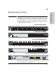
1 Introducing the Switch ProCurve Switch 2650 (J4899B) ProCurve Switch 2626 (J4900B) ProCurve Switch 2650-PWR (J8165A) hp procurve switch 2650-PWR J8165A 1 1 3 5 7 9 11 2 4 6 8 10 12 11 13 13 15 17 19 21 23 14 16 18 20 22 24 Link|Mode 23 25 25 27 29 31 33 35 26 28 30 32 34 36 35 37 37 39 41 43 45 47 38 40 42 44 46 48 47 Gig-T Ports PoE Status RPS Power Fault EPS Fan Act LED Mode 49 FDx M 50 M Spd Test PoE Reset Clear MiniGBIC Port
Introducing the Switch Introducing the Switch ■ The Switch 2650 and 2650-PWR, has 48 auto-sensing 10/100Base-TX RJ45 ports with two dual-personality Gigabit Uplink ports. ■ The Switch 2626 and 2626-PWR, has 24 auto-sensing 10/100Base-TX RJ45 ports with two dual-personality Gigabit Uplink ports. ■ The Switch 2600-8-PWR, has 8 auto-sensing 10/100Base-TX RJ-45 ports with one dual-personality Gigabit Uplink port.
Introducing the Switch Front of the Switch Power and Fault LEDs Self Test and Fan Status LEDs Power and Fault LEDs hp procurve switch 2650-PWR J8165A 1 ProCurve Switch 2650 Switch port LEDs 10/100Base-TX RJ-45 ports1 Port LED View select button and indicator LEDs Reset and Clear buttons RPS, EPS, Fan and Test Status LEDs 1 3 5 7 9 11 2 4 6 8 10 12 11 Dual-personality ports (1000Base-T2 or mini-GBIC) ProCurve Switch 2650-PWR Switch port LEDs 13 13 15 17 19 21 23 14 16 18
Introducing the Switch Front of the Switch Introducing the Switch Network Ports ■ 8, 24, or 48 auto-sensing 10/100Base-TX ports. All these ports have the “HP Auto MDIX” feature, which means that you can use either straight-through or crossover twisted-pair cables to connect any network devices to the switch. ■ Dual-personality ports. You can use either the 10/100/1000Base-T RJ-45 connector, or install a supported ProCurve mini-GBIC for fiber-optic connections.
Introducing the Switch Front of the Switch State Meaning Self Test (green) labeled “Test” on the PWR switches Off The normal operational state; the switch is not undergoing self test. On The switch self test and initialization are in progress after you have power cycled or reset the switch. The switch is not operational until this LED goes off. The Self Test LED also comes on briefly when you “hot swap” a mini-GBIC into the switch; the mini-GBIC is tested when it is hot swapped.
Introducing the Switch Front of the Switch Introducing the Switch Port LEDs The port LEDs provide information about the individual switch ports. Table 1-2. Switch LEDs Port LEDs State Meaning Switch 2626 and Switch 2650 Port LEDs (green – overlaid with the port number) Displays port link information, network activity information, whether the port is configured for full-duplex operation, or the speed of the connection depending on the Port LED View selected.
Introducing the Switch Front of the Switch To optimize the amount of information that can be displayed for each of the switch ports in the limited space available, the Series 2600 Switches use multiple-display LEDs for each port. Switch 2626 and Switch 2650 For the non-PWR switches, there is a single LED per port. The operation of this LED is controlled by the Port LED View select button, and the current setting is indicated by the Port LED View indicator LEDs near the button.
Introducing the Switch Front of the Switch Introducing the Switch Table 1-3. Switch LEDs Multiple-Display Port LEDs State Meaning Switch 2626 and Switch 2650 Port LED View indicator LEDs (4 green LEDs) Lnk Act FDx Spd Indicates that the Port LEDs are displaying link information: • if the Port LED is on, the port is enabled and receiving a link indication from the connected device.
Introducing the Switch Front of the Switch Reset Button Clear Button This button is used for these purposes: ■ Deleting Passwords - When pressed by itself for at least one second, the button deletes any switch console access passwords that you may have configured. Use this feature if you have misplaced the password and need console access.
Introducing the Switch Back of the Switch Introducing the Switch Back of the Switch ProCurve Switch 2626 and 2650 non-PWR Cooling vent - make sure this is not obstructed for proper switch operation Console Console Port AC power connector Cooling vent - make sure this is not obstructed for proper switch operation ProCurve Switch 2626-PWR and 2650-PWR HP ProCurve RPS Input 12V 7.5A Console Console Port Line 50/60 Hz. 100-240 V~ 7.
Introducing the Switch Switch Features Console Port Power Connector The Series 2600 Switches do not have a power switch; they are powered on when connected to an active AC power source. The switches automatically adjust to any voltage between 100-240 volts and either 50 or 60 Hz. There are no voltage range settings required. Switch Features The features of the Series 2600 Switches include: ■ 8, 24, or 48 auto-sensing 10/100Base-TX RJ-45 ports with HP Auto-MDIX.
Introducing the Switch Introducing the Switch Switch Features 1-12 ■ automatically negotiated full-duplex operation for the 10/100 and 10/100/1000 RJ-45 ports when connected to other auto-negotiating devices—the mini-GBIC ports always operate at full duplex. ■ easy management of the switches through several available interfaces: • console interface—a full featured, easy to use, VT-100 terminal interface that is especially good for out-of-band switch management or for Telnet access to the switch.
2 Installing the Switch The ProCurve Series 2600 Switches come with an accessory kit that includes the brackets for mounting the switch in a standard 19-inch telco rack, in an equipment cabinet, or on a wall. The brackets are designed to allow mounting the switch in a variety of locations and orientations. Rubber feet are provided that can be attached so the switch can be securely located on a horizontal surface.
Installing the Switch Included Parts Installing the Switch ■ AC power cord, one of the following: Australia/New Zealand China Continental Europe Denmark Japan Switzerland United Kingdom/Hong Kong/Singapore United States/Canada/Mexico South Africa Thailand Taiwan Non-PWR Switches and 2600-8-PWR PWR Switches 1 8120-6803 8120-8377 8120-6802 8120-6806 8120-6804 8120-6807 8120-8709 8120-6805 8120-8929 8121-0673 8121-0964 8120-6810 8120-8471 8120-6811 8120-6814 8120-6804 8120-6815 8120-6809 8120-2371 8120
Installing the Switch Installation Procedures Installation Procedures These steps summarize your switch installation. The rest of this chapter provides details on these steps. Prepare the installation site (page 2-5). Make sure the physical environment into which you will be installing the switch is properly prepared, including having the correct network cabling ready to connect to the switch and having an appropriate location for the switch. See page 2-4 for some installation precautions. 2.
Installing the Switch Installation Procedures Installation Precautions Follow these precautions when installing your ProCurve Series 2600 Switches. WARNING ■ The rack or cabinet should be adequately secured to prevent it from becoming unstable and/or falling over. Installing the Switch Devices installed in a rack or cabinet should be mounted as low as possible, with the heaviest devices at the bottom and progressively lighter devices installed above.
Installing the Switch Installation Procedures 1. Prepare the Installation Site ■ Cabling Infrastructure - Ensure the cabling infrastructure meets the necessary network specifications. See the following table for cable types and lengths, and see appendix B, “Switch Ports and Network Cables” for more information: Table 2-1.
Installing the Switch Installation Procedures Port Type Cable Type Length Limits Installing the Switch Fiber Optic Cables Gigabit-SX (on Gigabit-SX-LC mini-GBIC) Multimode fiber-optic cables fitted with LC connectors 220 meters to 550 meters depending on the cable used. See “Fiber-Optic Cables” on page B-2 for more information. Gigabit-LX (on Gigabit-LX-LC mini-GBIC) Single-mode fiber-optic cables fitted with LC connectors.
Installing the Switch Installation Procedures 2. Installing or Removing mini-GBICs You can install or remove a mini-GBIC from a mini-GBIC slot without having to power off the switch. Use only ProCurve mini-GBICs. Notes ■ The mini-GBIC slots are shared with the two 10/100/1000Base-T RJ-45 ports. If a mini-GBIC is installed in a slot, the associated RJ-45 port is disabled and cannot be used. ■ The mini-GBIC ports operate only at full duplex. Half duplex operation is not supported.
Installing the Switch Installation Procedures Removing the mini-GBICs Note You should disconnect the network cable from the mini-GBIC before removing it from the switch. Depending on when you purchased your ProCurve mini-GBIC, it may have either of three different release mechanisms: a plastic tab on the bottom of the mini-GBIC, a plastic collar around the mini-GBIC, or a wire bail.
Installing the Switch Installation Procedures 3. Verify the Switch Passes Self Test Before mounting the switch in its network location, you should first verify it is working properly by plugging it into a power source and verifying it passes its self test. 1. Connect the power cord supplied with the switch to the power connector on the back of the switch, and then into a properly grounded electrical outlet.
Installing the Switch Installation Procedures 2. Check the LEDs on the switch as described below. Switch 2650 Switch port LEDs Self Test LED Installing the Switch Power and Fault LEDs When the switch is powered on, it performs its diagnostic self test. Self test takes approximately 50 seconds to complete.
Installing the Switch Installation Procedures When the self test completes successfully: The Power and Fan Status LEDs remain on. • The Fault and Self Test LEDs go off. • The port LEDs on the front of the switch go into their normal operational mode: – If the ports are connected to active network devices, the LEDs behave according to the Port LED View or LED Mode selected. For the non-PWR switches, in the default view mode (Link), the LEDs should be on.
Installing the Switch Installation Procedures Equipment Cabinet Note The 12-24 screws supplied with the switch are the correct threading for standard EIA/TIA open 19-inch racks. If installing the switch in an equipment cabinet such as a server cabinet, use the clips and screws that came with the cabinet in place of the 12-24 screws that are supplied with the switch.
Installing the Switch Installation Procedures Note The mounting brackets have multiple mounting holes and can be rotated allowing for a wide variety of mounting options. These include mounting the switch so that its front face is flush with the face of the rack, or mounting it in a more balanced position as shown in the illustration above. 2.
Installing the Switch Installation Procedures Rack Mounting the Non-PWR Switches and the 2600-8-PWR Switch Use a #1 Phillips (cross-head) screwdriver and attach the mounting brackets to the switch with the included 8-mm M4 screws. Installing the Switch 1. 8 mm M4 screws Note The mounting brackets have multiple mounting holes and can be rotated allowing for a wide variety of mounting options.
Installing the Switch Installation Procedures 2. Hold the switch with attached brackets up to the rack and move it vertically until rack holes line up with the bracket holes, then insert and tighten the four number 12-24 screws holding the brackets to the rack.
Installing the Switch Installation Procedures Flat Wall Mounting You can mount the Non-PWR switches on a wall as shown in the illustration on the next page. However, this is not supported for the 2626-PWR or the 2650PWR switches. Wall mounting the PWR switches is not supported because of the size and weight of the devices. Wall mounting the 2600-8-PWR switch is supported. See page 2-18 for instructions.
Installing the Switch Installation Procedures Wall mounting the Series 2600 Non-PWR Switches 1. Use a #1 Phillips (cross-head) screwdriver and attach the mounting brackets to opposite corners of the switch with the included 8-mm M4 screws. 2. Attach the switch to the wall or wood surface with two 5/8-inch (15.875 mm) number 12 wood screws (not included).
Installing the Switch Installation Procedures Wall mounting the Series 2600-8-PWR Switch 1. Use a #1 Phillips (cross-head) screwdriver and attach the mounting brackets to the switch with the included 8-mm M4 screws. 2. Attach the switch to the wall or wood surface with two 5/8-inch number 12 wood screws (not included).
Installing the Switch Installation Procedures Horizontal Surface Mounting Place the switch on a table or other horizontal surface. The switch comes with rubber feet in the accessory kit that can be used to help keep the switch from sliding on the surface. Attach the rubber feet to the four corners on the bottom of the switch within the embossed angled lines. Use a sturdy surface in an uncluttered area.
Installing the Switch Installation Procedures 6. Connect the Network Cables Connect the network cables, described under “Cabling Infrastructure” (page 2-5), from the network devices or your patch panels to the fixed RJ-45 ports on the switch or to any mini-GBICs you have installed in the switch. Using the RJ-45 Connectors Installing the Switch To connect: Push the RJ-45 plug into the RJ-45 port until the tab on the plug clicks into place.
Installing the Switch Installation Procedures Connecting Cables to mini-GBICs Note The mini-GBIC slots are shared with the two 10/100/1000Base-T RJ-45 ports. If a mini-GBIC is installed in a slot, the associated RJ-45 port is disabled. If you have any mini-GBICs installed in the switch, the type of network connections you will need to use depends on the type of mini-GBICs you have installed.
Installing the Switch Installation Procedures RPS/EPS Operation The RPS/EPS monitors the power signal from the switch by detecting that the RPS/EPS is connected to a switch with an RPS/EPS cable. When the power from the switch is no longer detected, the RPS/EPS will turn on and provide power to the switch within 1 millisecond.
Installing the Switch Installation Procedures 600 RPS/EPS LEDs The 600 RPS/EPS LEDs are located on the back of the device. These LEDs are duplicated on the front of the device for your convenience. The following graphic shows an example of the back of the 600 EPS/RPS. There are two green LEDs for each RPS and EPS port: ■ Device Connected ■ Power Status RPS Power Status LED RPS Device Connected LED RPS 3 ! backup to one connected device. Lowest-numbered port has priority.
Installing the Switch Installation Procedures 600 RPS/EPS Connectivity The following illustration shows an example of connectivity between an RPS/ EPS device and a switch device as a redundant AC power supply. RPS Power: 12V RPS 1 Device Connected R1 Power Status RPS 2 R2 RPS 3 ! backup to one connected device. Lowest-numbered port has priority. R3 RPS 4 R4 RPS 5 R5 RPS 6 R6 EPS Power: 50V EPS 1 370W total for PoE applications. Power is shared when E1 both ports are used.
Installing the Switch Installation Procedures The following illustration shows an example of connectivity between an RPS/ EPS device and six switch devices as a redundant AC power supply. 2650-PWR switches Installing the Switch Highest priority connected to port 1 600 RPS/EPS The 600 RPS/EPS can provide backup power for up to six switches. The 600 RPS/EPS can supply power to only one connected and failed switch at a time.
Installing the Switch Installation Procedures The following illustration demonstrates an example of connectivity between an RPS/EPS device and a Switch device as a PoE power supply. RPS Power: 12V RPS 1 Device Connected R1 Power Status RPS 2 R2 RPS 3 EPS Power: 50V backup to one connected device. Lowest-numbered port has priority. R3 RPS 4 R4 RPS 5 R5 RPS 6 R6 EPS 1 370W total for PoE applications. Power is shared when E1 both ports are used.
Installing the Switch Installation Procedures 610 EPS LEDs Power and Fault LEDs Backup Power Port LEDs hp procurve EPS Ports Pair A (408 W total for PoE applications) 610 eps EPS A1 J8169A Power A1 Device Connected Power Status EPS A2 EPS Ports A2 Pair B (408 W total for PoE applications) EPS B1 B1 Device Connected Power Status EPS B2 B2 Backup Power Ports Status Internal Power Status Fan/Temp Status Fault 610 EPS EPS Port LEDs In Ready Out Ready EPS Ports: 50V 8.3A max each.
Installing the Switch Installation Procedures 50 V 16 A 50 V 16 A 12 V RPS 7.5 A 12 V RPS 7.5 A hp procurve Line: 50/60 Hz. 100-240 V~ 7.5 A Line: 50/60 Hz. 100-240 V~ 7.
Installing the Switch Installation Procedures 16 A 50 V 16 A 50 V 16 A 50 V 16 A 12 V RPS 7.5 A 12 V RPS 7.5 A 12 V RPS 7.5 A 12 V RPS 7.5 A hp procurve Line: 50/60 Hz. 100-240 V~ 7.5 A Line: 50/60 Hz. 100-240 V~ 7.5 A Line: 50/60 Hz. 100-240 V~ 7.5 A Line: 50/60 Hz. 100-240 V~ 7.
Installing the Switch Installation Procedures 8.
Installing the Switch Installation Procedures Direct Console Access To connect a console to the switch, follow these steps: Console 1. Console port Console cable supplied with the switch Installing the Switch Connect the PC or terminal to the switch’s Console Port using the console cable included with the switch. (If your PC or terminal has a 25-pin serial connector, first attach a 9-pin to 25-pin straight-through adapter at one end of the console cable.
Installing the Switch Sample Network Topologies for Non-PWR Switches Sample Network Topologies for Non-PWR Switches This section shows a few sample network topologies in which the Switch 2650 is implemented. For more topology information, see the ProCurve networking products Web site, http://www.procurve.com.
Installing the Switch Sample Network Topologies for Non-PWR Switches As a Segment Switch Category 5e twisted-pair straight-through or crossover cable for 1000 Mbps connection to server Server with Gigabit Ethernet NIC Gigabit fiber-optic cable to backbone Switch 2650 Twisted-pair straight-through or crossover cables to hubs Installing the Switch Switch 2650 Switch 2650 Twisted-pair straight-through cables to end nodes PCs, printers, and local servers The Series 2600 Switches also work well as segme
Installing the Switch Sample Network Topologies for Non-PWR Switches Because the Series 2600 Switches have the “HP Auto-MDIX” and “IEEE Auto MDI/MDI-X” features, the connections between the switch and the hubs, and between the switch and end nodes or servers can be through category 5 straight-through or crossover twisted-pair cable. Category 3 or 4 cable can also be used if the connection is 10 Mbps only.
Installing the Switch Sample Network Topologies for Non-PWR Switches Connecting to a Backbone Switch To Gigabit-Ethernet backbone Switch 5308xl Switch 2650 Installing the Switch Gigabit fiber-optic cables Switch 2650 Switch 2650 Switch 2650 The simpler desktop and segment networks shown in the previous two examples can easily be combined and expanded. For example, you could use an ProCurve Switch 5308xl to interconnect each of your smaller switched workgroups to form a larger switched network.
Installing the Switch Sample Network Topologies for PWR Switches Sample Network Topologies for PWR Switches This section shows a few sample network topologies implementing the Series 2600-PWR Switches. For more topology information, see the ProCurve networking products Web site, http://www.procurve.com.
Installing the Switch Sample Network Topologies for PWR Switches As a Segment Switch Implementing PoE Category 5e twisted-pair straight-through or crossover cable for 1000 Mbps connection to server Server with Gigabit Ethernet NIC 600 RPS/EPS Switch 2650 Non-PWR Gigabit fiber-optic cable uplink Switch 2600-8-PWR * Spd mode: ProCur ve of f = 10 Mbps, flash = 0 10 Mbps, on = 0 100 Mbps Switc h 2600-PWR J8762A Link Act RPS Fault EPS Fan Dual-Personality P ort: 10/1 00/1 000-T (T) o r Mini-GBIC
Installing the Switch Sample Network Topologies for PWR Switches Connecting to a Backbone Switch Implementing PoE To Gigabit-Ethernet backbone Switch 5308xl Installing the Switch Switch 2650 Gigabit fiber-optic cable Switch 2650 non-PWR Switch 2650-PWR Wireless Access Point 2-38 600 RPS/EPS Switch 2650-PWR
Installing the Switch Sample Network Topologies for PWR Switches Stacking the Switch Switch 2600 and 2600-PWR Series devices can be connected together, through standard network connections, and managed through a single IP address. Up to 16 switches can be connected together in such a “virtual stack”. You identify a Switch 2600 or 2600-PWR Series device as the “Commander” and give that switch an IP address.
— This page is intentionally unused.
3 Configuring the Switch This chapter is a guide for using the console Switch Setup screen to quickly assign an IP (Internet Protocol) address and subnet mask to the switch, set a Manager password, and, optionally, configure other basic features. For more information on using the switch console and the web browser interface, please see the Management and Configuration Guide, which is on the Documentation CD-ROM that came with your switch.
Configuring the Switch Note By default, the switch is configured to acquire an IP address configuration from a DHCP or Bootp server. To use DHCP/Bootp instead of the manual method described in this chapter, see “DHCP/Bootp Operation” in the Management and Configuration Guide, which is on the Documentation CD-ROM that came with your switch.
Configuring the Switch 4. [Tab] to the IP Config (DHCP/Bootp) field and use the Space bar to select the Manual option. 5. [Tab] to the IP Address field and enter the IP address that is compatible with your network. 6. [Tab] to the Subnet Mask field and enter the subnet mask used for your network. 7. Press [Enter], then [S] (for Save). Here is some information on the fields in the Setup screen.
Configuring the Switch Where to Go From Here The above procedure configures your switch with a Manager password, IP address, and subnet mask. As a result, with the proper network connections, you can now manage the switch from a PC equipped with Telnet, and/or a web browser interface. Some basic information on managing your switch is included in the next section.
Configuring the Switch Using the IP Address for Remote Switch Management Using the IP Address for Remote Switch Management With your switch, you can use the switch’s IP address to manage the switch from any PC that is on the same subnet as the switch. You can use either a Telnet session or a standard web browser to manage the switch. Starting a Telnet Session To access the switch through a Telnet session, follow these steps: 1.
Configuring the Switch Using the IP Address for Remote Switch Management For more information on using the web browser interface, please see the Management and Configuration Guide, which is on the Documentation CD-ROM that came with your switch. Configuring the Switch An extensive help system is also available for the web browser interface. To access the help system though, the subnet on which the switch is installed must have access to the internet.
4 Troubleshooting This chapter describes how to troubleshoot your ProCurve Series 2600 Switch. This document describes troubleshooting mostly from a hardware perspective. You can perform more in-depth troubleshooting on these devices using the software tools available with the switches, including the fullfeatured console interface, the built-in web browser interface, and ProCurve Manager, the SNMP-based network management tool.
Troubleshooting Basic Troubleshooting Tips Caution Because the Series 2600 Switches behave in this way (in compliance with the IEEE 802.3 standard), if a device connected to the switch has a fixed configuration at full duplex, the device will not connect correctly to the switch. The result will be high error rates and very inefficient communications between the switch and the device.
Troubleshooting Basic Troubleshooting Tips ■ Check the port configuration. A port on your switch may not be operating as you expect because it has been put into a “blocking” state by Spanning Tree, GVRP (automatic VLANs), or LACP (automatic trunking). (Note that the normal operation of the Spanning Tree, GVRP, and LACP features may put the port in a blocking state.) Or, the port just may have been configured as disabled through software.
Troubleshooting Diagnosing with the LEDs Diagnosing with the LEDs Table 4-1 shows LED patterns on the switch and the switch modules that indicate problem conditions. 1. Check in the table for the LED pattern you see on your switch. 2. Refer to the corresponding diagnostic tip on the next few pages. Table 4-1.
Troubleshooting Diagnosing with the LEDs Diagnostic Tips: Problem Solution ➊ The switch is not plugged into an active AC power source, or the switch’s power supply may have failed. 1. Verify the power cord is plugged into an active power source and to the switch. Make sure these connections are snug. 2. Try power cycling the switch by unplugging and plugging the power cord back in. 3. If the Power LED is still not on, verify the AC power source works by plugging another device into the outlet.
Troubleshooting Diagnosing with the LEDs Tip Problem Solution ➏ The network connection is not working properly. Try the following procedures: • For the indicated port, verify that both ends of the cabling, at the switch and the connected device, are connected properly. • Verify the connected device and switch are both powered on and operating correctly.
Troubleshooting Diagnosing with the LEDs Tip Problem Solution ➐ The port may be improperly configured, or the port may be in a “blocking” state by the normal operation of the Spanning Tree, LACP, or IGMP features. Use the switch console to see if the port is part of a dynamic trunk (through the LACP feature) or to see if Spanning Tree is enabled on the switch, and to see if the port may have been put into a “blocking” state by those features.
Troubleshooting Proactive Networking Proactive Networking The ProCurve Series 2600 Switches have built-in management capabilities that proactively help you manage your network including: ■ finding and helping you fix the most common network error conditions (for example, faulty network cabling, and non-standard network topologies) ■ informing you of the problem with clear, easy-to-understand messages ■ recommending network configuration changes to enhance the performance of your network The following
Troubleshooting Hardware Diagnostic Tests Hardware Diagnostic Tests Testing the Switch by Resetting It If you believe the switch is not operating correctly, you can reset the switch to test its circuitry and operating code.
Troubleshooting Hardware Diagnostic Tests Testing Twisted-Pair Cabling Network cables that fail to provide a link or provide an unreliable link between the switch and the connected network device may not be compatible with the IEEE 802.3 Type 10Base-T, 100Base-TX, or 1000Base-T standards. The twistedpair cables attached to the switch must be compatible with the appropriate standards. To verify your cable is compatible with these standards, use a qualified cable test device.
Troubleshooting Restoring the Factory Default Configuration Restoring the Factory Default Configuration As part of your troubleshooting process on the Switch, it may become necessary to return the switch configuration to the factory default settings. This clears any passwords, clears the console event log, resets the network counters to zero, performs a complete self test, and reboots the switch into its factory default configuration including deleting the IP address, if one is configured.
Troubleshooting Downloading New Switch Software Downloading New Switch Software When product enhancements occur for the Series 2600 Switches, new software can be downloaded to the switch through several methods, for product enhancements and new features. For more information, see the Management and Configuration Guide, which is on the Documentation CDROM that came with your switch. The new switch software would be available on the ProCurve Web site, http://www.procurve.com.
A Switch Specifications Switch Specifications Physical Width Depth Height Weight 2626 (J4900B) 44.3 cm (17.4 in) 36.7 cm (14.4 in) 4.4 cm (1.73 in) 4.62 kg (10.20 lbs) 2650 (J4899B) 44.3 cm (17.4 in) 43.0 cm (16.9 in) 4.4 cm (1.73 in) 4.88 kg (10.75 lbs) 2600-8-PWR (J8762A) 44.3 cm (17.4 in) 22.5 cm (8.86 in) 4.4 cm (1.73 in) 3.4 kg (7.5 lbs) 2626-PWR (J8164A) 44.3 cm (17.4 in) 48.3 cm (19.0 in) 4.4 cm (1.73 in) 6.84 kg (15.05 lbs) 2650-PWR (J8165A) 44.3 cm (17.4 in) 48.3 cm (19.
Switch Specifications Switch Specifications Environmental Non-PWR 2600 Series Operating Non-Operating Temperature 0 °C to 55 °C (32 °F to 131 °F) -40 °C to 70 °C (-40 °F to 158 °F) Relative humidity (non-condensing) 15% to 95% at 40 °C (104 °F) 15% to 90% at 65 °C (149 °F) Maximum altitude 4.6 Km (15,000 ft) 4.
Switch Specifications Connectors The 10/100/1000 Mbps RJ-45 twisted-pair ports are compatible with the following standards: • IEEE 802.3ab 1000Base-T • IEEE 802.3u 100Base-TX • IEEE 802.3 10Base-T ■ The 1000 Mbps LC fiber-optic ports on the Gigabit-SX and Gigabit-LX miniGBIC transceivers are compatible with the IEEE 802.3z Gigabit-SX and Gigabit-LX standards. ■ EPS connector: A 2x7 Molex Micro-Fit connector should be used for EPS connection.
— This page is intentionally unused.
B Switch Ports and Network Cables This appendix includes switch connector information and network cable information for cables that should be used with the Switch 2600 and 2600-PWR Series devices, including minimum pin-out information and specifications for twisted-pair cables. Incorrectly wired cabling is the most common cause of problems for LAN communications. HP recommends that you work with a qualified LAN cable installer for assistance with your cabling requirements.
Switch Ports and Network Cables Because of the increased speed provided by 1000Base-T (Gigabit-T), network cable quality is more important than for either 10Base-T or 100Base-TX. Cabling plants being used to carry 1000Base-T networking must comply with the IEEE 802.3ab standards. In particular, the cabling must pass tests for Attenuation, Near-End Crosstalk (NEXT), and Far-End Crosstalk (FEXT).
Switch Ports and Network Cables Mode Conditioning Patch Cord for Gigabit-LX Mode Conditioning Patch Cord for Gigabit-LX The following information applies to installations in which multimode fiberoptic cables are connected to a Gigabit-LX port. Gigabit-LX mini-GBICs, since they are designed to operate with both singlemode and multimode cable, do not provide the transmission conditioning internally.
Switch Ports and Network Cables Mode Conditioning Patch Cord for Gigabit-LX Installing the Patch Cord As shown in the illustration below, connect the patch cord to the Gigabit-LX mini-GBIC with the section of single-mode fiber plugged in to the Tx (transmit) port. Then, connect the other end of the patch cord to your network cabling patch panel, or directly to the network multimode fiber.
Switch Ports and Network Cables Twisted-Pair Cable/Connector Pin-Outs Twisted-Pair Cable/Connector Pin-Outs The HP Auto-MDIX Feature: In the default configuration, “Auto”, the fixed 10/100Base-TX ports on the Series 2600 Switches all automatically detect the type of port on the connected device and operate as either an MDI or MDI-X port, whichever is appropriate.
Switch Ports and Network Cables Switch Ports and Network Cables Twisted-Pair Cable/Connector Pin-Outs B-6 ■ For 100 Mbps connections to the ports, use 100-ohm Category 5 UTP or STP cable only, as supported by the IEEE 802.3u Type 100Base-TX standard. ■ For 1000 Mbps connections, 100-ohm Category 5e or better cabling is recommended.
Switch Ports and Network Cables Twisted-Pair Cable/Connector Pin-Outs Straight-through Twisted-Pair Cable for 10 Mbps or 100 Mbps Network Connections Because of the HP Auto-MDIX operation of the 10/100 ports on the switch, for all network connections, to PCs, servers or other end nodes, or to hubs or other switches, you can use straight-through cables.
Switch Ports and Network Cables Twisted-Pair Cable/Connector Pin-Outs Crossover Twisted-Pair Cable for 10 Mbps or 100 Mbps Network Connection The HP Auto-MDIX operation of the 10/100 ports on the switch also allows you to use crossover cables for all network connections, to PCs, servers or other end nodes, or to hubs or other switches.
Switch Ports and Network Cables Twisted-Pair Cable/Connector Pin-Outs Straight-Through Twisted-Pair Cable for 1000 Mbps Network Connections 1000Base-T connections require that all four pairs of wires be connected. Cable Diagram Switch Ports and Network Cables Note Pins 1 and 2 on connector “A” must be wired as a twisted pair to pins 1 and 2 on connector “B”. Pins 3 and 6 on connector “A” must be wired as a twisted pair to pins 3 and 6 on connector “B”.
— This page is intentionally unused.
C Safety and EMC Regulatory Statements Safety Information ! Documentation reference symbol. If the product is marked with this symbol, refer to the product documentation to get more information about the product. WARNING A WARNING in the manual denotes a hazard that can cause injury or death. Caution A Caution in the manual denotes a hazard that can damage equipment. Do not proceed beyond a WARNING or Caution notice until you have understood the hazardous conditions and have taken appropriate steps.
Safety and EMC Regulatory Statements Informations concernant la sécurité Informations concernant la sécurité ! Symbole de référence à la documentation. Si le produit est marqué de ce symbole, reportez-vous à la documentation du produit afin d'obtenir des informations plus détaillées. WARNING Dans la documentation, un WARNING indique un danger susceptible d'entraîner des dommages corporels ou la mort.
Safety and EMC Regulatory Statements Hinweise zur Sicherheit Hinweise zur Sicherheit ! Symbol für Dokumentationsverweis. Wenn das Produkt mit diesem Symbol markiert ist, schlagen Sie bitte in der Produktdokumentation nach, um mehr Informationen über das Produkt zu erhalten. WARNING Eine WARNING in der Dokumentation symbolisiert eine Gefahr, die Verletzungen oder sogar Todesfälle verursachen kann. Caution Caution in der Dokumentation symbolisiert eine Gefahr, die dis Gerät beschädigen kann.
Safety and EMC Regulatory Statements Considerazioni sulla sicurezza Considerazioni sulla sicurezza ! Simbolo di riferimento alla documentazione. Se il prodotto è contrassegnato da questo simbolo, fare riferimento alla documentazione sul prodotto per ulteriori informazioni su di esso. WARNING La dicitura WARNINGdenota un pericolo che può causare lesioni o morte. Caution La dicituraCaution denota un pericolo che può danneggiare le attrezzature.
Safety and EMC Regulatory Statements Consideraciones sobre seguridad Consideraciones sobre seguridad ! Símbolo de referencia a la documentación. Si el producto va marcado con este símbolo, consultar la documentación del producto a fin de obtener mayor información sobre el producto. WARNING Una WARNING en la documentación señala un riesgo que podría resultar en lesiones o la muerte. Caution Una Caution en la documentación señala un riesgo que podría resultar en averías al equipo.
Safety and EMC Regulatory Statements Safety Information (Japan) Safety and EMC Regulatory Statements Safety Information (Japan) Japan Power Cord Warning C-6
Safety and EMC Regulatory Statements Safety Information (China) Safety Information (China) Safety and EMC Regulatory Statements C-7
Safety and EMC Regulatory Statements EMC Regulatory Statements EMC Regulatory Statements U.S.A. FCC Class A This equipment has been tested and found to comply with the limits for a Class A digital device, pursuant to Part 15 of the FCC Rules. These limits are designed to provide reasonable protection against interference when the equipment is operated in a commercial environment.
Safety and EMC Regulatory Statements EMC Regulatory Statements Korea Taiwan Safety and EMC Regulatory Statements C-9
Safety and EMC Regulatory Statements EMC Regulatory Statements European Community DECLARATION OF CONFORMITY according to ISO/IEC Guide 22 and EN45014 Manufacturer's Name: Hewlett-Packard Company Manufacturer's Address: 8000 Foothills Blvd Roseville, CA 95747-5502 U.S.A.
Safety and EMC Regulatory Statements EMC Regulatory Statements DECLARATION OF CONFORMITY according to ISO/IEC Guide 22 and EN45014 Manufacturer's Name: Hewlett-Packard Company Manufacturer's Address: 8000 Foothills Blvd Roseville, CA 95747-5502 U.S.A. declares that the product: Product Name: ProCurve Switch 2626-PWR ProCurve Switch 2650-PWR ProCurve Switch 2600-8-PWR Model Number: J8164A, J8165A, J8762A, J8169A1 Accessories: J4858A, J4859A, J4860A, J8168A.
Safety and EMC Regulatory Statements Waste Electrical and Electronic Equipment (WEEE) Statements Waste Electrical and Electronic Equipment (WEEE) Statements Disposal of Waste Equipment by Users in Private Household in the European Union This symbol on the product or on its packaging indicates that this product must not be disposed of with your other household waste.
Safety and EMC Regulatory Statements Waste Electrical and Electronic Equipment (WEEE) Statements Laitteiden hävittäminen kotitalouksissa Euroopan unionin alueella Jos tuotteessa tai sen pakkauksessa on tämä merkki, tuotetta ei saa hävittää kotitalousjätteiden mukana. Tällöin hävitettävä laite on toimitettava sähkölaitteiden ja elektronisten laitteiden kierrätyspisteeseen.
Safety and EMC Regulatory Statements Waste Electrical and Electronic Equipment (WEEE) Statements Smaltimento delle apparecchiature da parte di privati nel territorio dell'Unione Europea Questo simbolo presente sul prodotto o sulla sua confezione indica che il prodotto non può essere smaltito insieme ai rifiuti domestici. È responsabilità dell'utente smaltire le apparecchiature consegnandole presso un punto di raccolta designato al riciclo e allo smaltimento di apparecchiature elettriche ed elettroniche.
Safety and EMC Regulatory Statements Waste Electrical and Electronic Equipment (WEEE) Statements Descarte de Lixo Elétrico na Comunidade Européia Este símbolo encontrado no produto ou na embalagem indica que o produto não deve ser descartado no lixo doméstico comum. É responsabilidade do cliente descartar o material usado (lixo elétrico), encaminhando-o para um ponto de coleta para reciclagem.
— This page is intentionally unused.
Index Numerics 10/100Base-TX ports location on switch … 1-3 1000Base-LH connections, length limitations … 2-6 ports, cables used with … 2-6 1000Base-LX connections, length limitations … 2-6 ports, cables used with … 2-6 1000Base-SX connections, length limitations … 2-6 ports, cables used with … 2-6 1000Base-T connections, length limitations … 2-5 ports, cables used with … 2-5 600 RPS/EPS cables … 2-22 connectivity … 2-24 LEDs … 2-23 operating characteristics … 2-22 610 EPS cables … 2-27 connectivity … 2-28
Index cables, twisted pair category 3, 4, 5 … B-5 cross-over cable pin-out … B-8 MDI-X to MDI connections … B-7, B-9 MDI-X to MDI-X connections … B-8 pin-outs … B-7, B-9 straight-through cable pin-out … B-7, B-9 switch-to-computer connection … B-7, B-9 switch-to-switch or hub connection … B-8 cables, twisted-pair HP Auto-MDIX feature … B-5 wiring rules … B-5 cables, twisted-pair connector pin-outs … B-5 cabling infrastructure … 2-5 Clear button deleting passwords … 1-9 description … 1-9 location on switch
Fault LED … 1-4 behavior during self test … 2-11 behaviors … 1-4 blinking definition … 1-5–1-6, 1-8 location on switch … 1-3 showing error conditions … 4-4 features console … 2-30 switch … 1-11 fiber-optic cables … B-2 1000Base-LH … B-2 1000Base-LX … B-2 1000Base-SX … B-2 front of switch … 1-3 10/100Base-TX ports … 1-3 Clear button … 1-9 description … 1-3 dual-personality ports … 1-4 LEDs … 1-4 network ports … 1-4 Reset button … 1-9 full-duplex fixed configuration effects on network connections … 4-1 full-d
mini-GBICs full-duplex operation … 2-7 slot, location on switch … 1-3 mounting the switch in a rack or cabinet … 2-11 precautions … 2-4 on a horizontal surface … 2-19 on a wall … 2-16 precautions … 2-16 Multiple-Display Port LEDs … 1-7 N network cables 1000Base-LH connections … 2-6 1000Base-LX connections … 2-6 1000Base-SX connections … 2-6 1000Base-T connections … 2-5 fiber-optic, specifications … B-2 HP Auto-MDIX feature … B-5 required types … 2-5 twisted-pair connector pin-outs … B-5 twisted-pair, wirin
resetting the switch factory default reset … 4-11 location of Reset button … 1-9 troubleshooting procedure … 4-9 RPS/EPS … 2-21 cables … 2-22 connecting to a switch … 2-24–2-26 operation … 2-22 S T Telnet access to the console … 3-5 terminal configuration … 2-30 testing checking the console messages … 4-9 checking the LEDs … 4-9 diagnostic tests … 4-9 end-to-end communications … 4-10 link test … 4-10 Ping test … 4-10 switch operation … 4-9 switch-to-device communications … 4-10 twisted-pair cabling … 4-10
troubleshooting … 4-1 basic tips … 4-1 checking port configuration … 4-3 checking the console messages … 4-9 checking the LEDs … 4-9 common network problems … 4-1 connecting to fixed full-duplex devices … 4-1 diagnostic tests … 4-9 effects of improper topology … 4-2 effects of non-standard cables … 4-2 link test … 4-10 Ping test … 4-10 Proactive Network tools … 4-8 restoring factory default configuration … 4-11 testing connections to other devices … 4-10 testing end-to-end communications … 4-10 testing the
Technical information in this document is subject to change without notice. © Copyright 2001, 2005, 2008 Hewlett-Packard Development Company, L.P. Reproduction, adaptation, or translation without prior written permission is prohibited except as allowed under the copyright laws.