Installation and Getting Started Guide HP ProCurve Secure Access 700wl Series www.hp.
HP PROCURVE SECURE ACCESS 700WL SERIES INSTALLATION AND GETTING STARTED GUIDE
© Copyright 2004 Hewlett-Packard Development Company, L.P. The information contained herein is subject to change without notice. This document contains proprietary information, which is protected by copyright. No part of this document may be photocopied, reproduced, or translated into another language without the prior written consent of Hewlett-Packard.
CONTENTS Preface vii Audience vii Document Objectives vii Organization vii Related Publications Chapter 1 viii Document Conventions ix Support Information ix Introduction to the HP ProCurve 700wl Series 1-1 Overview 1-1 Centralized Administration of the 700wl Series system 1-1 Order of Network Installation 1-2 Access Control Server With One or More Access Controllers 1-2 Integrated Access Manager Only 1-3 Integrated Access Manager With Additional Access Controllers 1-3 Redundant Access
Rack Mounting the Chassis Connecting Power to the Chassis Chapter 3 Chapter 4 iv 2-10 2-11 Adding an Option Card Removing the Top and Option Card Cover Plate Inserting an Option Card into a 700wl Series Unit 2-11 2-12 2-13 Network Setup 3-1 Getting Started 3-1 Access Control Server or Integrated Access Manager Setup IP Addressing Considerations Configuration Using the Command Line Interface Configuration Using the Administrative Console 3-2 3-2 3-3 3-7 Access Controller Setup IP Addressing Cons
Appendix C Technical Specifications, Safety and Compliance Technical Specifications Environmental Ranges Power Requirements Physical Dimensions Safety and Regulatory Compliance Physical Interface Appendix D Appendix E C-1 C-1 C-1 C-1 C-2 C-2 C-2 Cable and Connector Specifications D-1 Serial Connector D-1 10/100 Downlink Ethernet Connectors D-2 Option Card Ports and Cables Ports Cables D-2 D-2 D-3 Safety and EMC Regulatory Statements E-1 Safety Information U.S.A.
vi Installation and Getting Started Guide
PREFACE This preface describes the objective, audience, use, and organization of the Installation and Getting Started Guide. It also outlines the document conventions, related documentation, and support information. Audience The audience for this document is the network administrator who wants to enable network users to communicate using the 700wl Series system.
Chapter 2– Hardware Installation This chapter describes the installation of the HP ProCurve Access Control Server 740wl, and Access Controller 720wl. Chapter 3– Network Setup This chapter describes the network configuration of the Access Control Server after it has been physically installed.
Document Conventions The following text conventions are used in this document: Convention Definition Boldface Arial Screen menus that you click to select, field names, and commands that you select are in boldface Arial. Italic Palatino New terms that are defined in the text, and emphasized terms are in italic Palatino. Courier Filenames and commands or text that you type are in Courier. The following icons are used to alert you to important information: Icon Notice Type Alerts you to...
x HP ProCurve Secure Access 700wl Series Installation and Getting Started Guide
INTRODUCTION TO THE HP PROCURVE 700WL SERIES 1 This chapter gives a brief description of the installation procedures for HP ProCurve 700wl Series products. It consists of the following sections Overview . . . . . . . . . . . . . . . . . . . . . . . . . . . . . . . . . . . . . . . . . . . . . . . . . . . . . . . . . . . . . . . . . . 1-1 Order of Network Installation . . . . . . . . . . . . . . . . . . . . . . . . . . . . . . . . . . . . . . . . . . . . . . . . . 1-2 Tools and Information Required . . . .
Introduction to the HP ProCurve 700wl Series • Set up Identity Profiles to put users in groups that share the same access policies • Set up Connection Profiles that allow you to specify different Access Policies for users based on location, time of day, VLAN tags, and Authentication Policies • Set up redundant Access Control Servers to provide failover Additionally, the Administrative Console provides functions for monitoring the status of the system components, as well as monitoring clients logged o
Introduction to the HP ProCurve 700wl Series Integrated Access Manager Only If you are installing an Integrated Access Manager 760wl only, perform installation in the following order: Step 1. Install the Integrated Access Manager, following the steps in the HP ProCurve 700wl Series Quick Start Guide included in the Documentation Kit that came with the unit, or in Chapter 2, “Hardware Installation” in this manual. Step 2.
Introduction to the HP ProCurve 700wl Series Step 6. On the Primary Access Control Server, configure redundancy, following the steps in Chapter 6, “Configuring the Network” in the HP ProCurve Secure Access 700wl Series Management and Configuration Guide for software Version 4.0.
HARDWARE INSTALLATION 2 This chapter describes the hardware installation of the following HP ProCurve products: Access Control Server 740wl, Access Controller 720wl, and Integrated Access Manager 760wl. You must be sure that the site requirements are met and carefully follow the procedures described to physically install the equipment. This chapter consists of the following sections: Hardware Description . . . . . . . . . . . . . . . . . . . . . . . . . . . . . . . . . . . . . . . . . . . . . . . . . . .
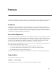
Hardware Installation Figure 2-2. Access Control Server 740wl ON HD hp ac proc ce J8 ss urve 15 co 4A nt rol se rver D 74 0w l SC RO LL SE LE CT RES ER VE N D ET W U PL OR IN K K 1 2 3 1 2 3 4 The hardware for all three products is very similar, and consists of a chassis, power supply, fans, I/O ports, indicators, and switches. All systems have at least two RJ45 connectors—one for the network uplink, used to connect the system to the network, and one that is reserved for future use.
Hardware Installation System Memory/Storage The Access Control Server 740wl and Integrated Access Manager 760wl are each equipped with a hard disk; the Access Controller 720wl is equipped with 256K of flash memory. Figure 2-5 shows an Integrated Access Manager 760wl with the top cover removed. An Access Control Server 740wl looks similar, but without the riser board, into which option cards are inserted. Figure 2-5.
Hardware Installation Chassis The chassis is a 2 rack-unit (RU) enclosure, having dimensions 17.00” (43.2 cm) wide, 15.00” (38.1 cm) deep, and 3.5” (8.9 cm) high. It weighs 14 lbs (6.4 kg). It can be mounted at the front with the brackets provided. Power Supply A single, non-redundant, auto voltage sensing power supply is provided. Input is 100-240 volts, 2.5A, 50/60 Hz, with a measured 87 watts output. Fans Note: For environmental specifications, see —Site Power Requirements and Heat Dissipation“.
Hardware Installation Table 2-1. I/O Ports Number of Ports Port Function Description 740wl 760wl 720wl Network Uplink RJ45, 10Base-T/ 100Base-TX/1000Base-T 1 1 1 Reserved port (for future use) RJ45, 10Base-T/ 100Base-TX/1000Base-T 1 1 1 Serial Console DB9, Serial Port 1 1 1 Access Controller Downlink Port RJ45, 10Base-T/100Base-TX 0 up to 12 up to 12 Controls and Indicators Controls There is only one control on the front of the chassis, a power button, labeled I/0.
Hardware Installation LCD Display The display can be used to view the system’s network parameters, and to power down the system. The LCD display is located in the middle of the front panel of 700wl Series products. It is a 16 character by two line display, with two buttons located to the right of the display (Figure 2-8). Figure 2-8. LCD Display SCROLL SELECT Appendix B, “LCD Display Description” describes the messages and operation of the LCD display panel.
Hardware Installation Figure 2-10. Access port labeling on an Access Controller or Integrated Access Manager 1 Left LED 2 3 4 Right LED Cluster LEDs Table 2-3 shows the possible states for each LED and the meaning of each state. Table 2-3.
Hardware Installation Site Planning Checklist Before installing an Integrated Access Manager 760wl, Access Control Server 740wl, or Access Controller 720wl, you should evaluate the items in the following site planning checklist: Space Evaluation • Space and layout • Floor covering • Impact and vibration • Lighting • Maintenance access Environmental Evaluation • Ambient temperature • Humidity • Altitude • Atmospheric contamination • Airflow Power Evaluation • Input power type • Proxi
Hardware Installation Site Power Requirements and Heat Dissipation Table 2-4 shows the site power requirements and heat dissipation for the Integrated Access Manager 760wl, Access Control Server 740wl, and Access Controller 720wl. Table 2-4. Site Power Requirements, Temperature and Heat Dissipation Parameters Parameter Value Power Supply Output (Watts) 56 AC Input Power (Watts) 80 Heat Dissipation (BTU/Hr.) 170 AC Input Current at 120 VAC (Amps) .88 AC Input Current at 240 VAC (Amps) .
Hardware Installation Rack Mounting the Chassis Each 700wl Series chassis comes with attached L-brackets suitable for mounting the chassis in a standard 19-inch (48.3 cm) equipment rack with two unobstructed outer posts. This unit is not suitable for mounting in racks with obstructions (such as a power strip) that could impair access to the device. The air space in front and rear of system should be 6.00 in. minimum. Caution: Ground the chassis properly with the supplied power cord.
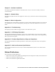
Hardware Installation c. Use the tape measure and level to ensure that the chassis is installed straight and level. Figure 2-12. Mounting the Integrated Access Manager 760wl in a rack or cabinet . ON HD D hp inte proc ur J8 grat ve 15 5A ed ac ce ss man ag er 76 0w l SC RO LL SE LE C T 1 RE SE RV ED NET W UP OR LIN K K 2 3 1 2 3 4 Connecting Power to the Chassis Follow these steps to connect power to the chassis: Step 1.
Hardware Installation Warning: Blank option card cover plates and cover panels serve three important functions: they prevent exposure to hazardous voltages and currents inside the chassis; they contain electromagnetic interference (EMI) that might disrupt other equipment; and they direct the flow of cooling air through the chassis. Do not operate the system unless all cards, option card cover plates, front covers, and rear covers are in place.
Hardware Installation Inserting an Option Card into a 700wl Series Unit Step 1. Remove the option card from its protective packaging, taking care not to damage it. Step 2. Insert the card into the chassis as shown (Figure 2-14). Figure 2-14. Inserting an option card into the 700wl Series chassis Riser Board ON HD D hp ac pro c cu J8 ess rv 15 c e 3A on tro lle r7 20 wl SC RO LL SE L EC T RE SE RV E D NE TW U P OR LIN K K 1 Option card Retaining Screw Cover 2 3 4 Step 3.
Hardware Installation 2-14 HP ProCurve Secure Access 700wl Series Installation and Getting Started Guide
NETWORK SETUP 3 This chapter describes the network setup of your 700wl Series equipment on an existing network to allow interoperability and proper network security for all equipment. It consists of the following sections: Getting Started . . . . . . . . . . . . . . . . . . . . . . . . . . . . . . . . . . . . . . . . . . . . . . . . . . . . . . . . . . . . . . 3-1 Access Control Server or Integrated Access Manager Setup . . . . . . . . . . . . . . . . . . . . . . . 3-2 Access Controller Setup . . . . . .
Network Setup first be configured with the IP address of the Access Control Server, and the shared secret used to validate the Access Controller to its Access Control Server. The Access Controller does not have a browser-based Administrative Console of its own, so this initial configuration must be done using the CLI via the serial console port. Note: If you plan to use an option card port (i.
Network Setup If you elect to obtain the Access Control Server IP address using DHCP, the Access Control Server can also obtain the hostname, domain name, subnet mask, default router address, and primary and secondary DNS server addresses from the DHCP server. Which information it receives depends on how you have configured your DHCP server.
Network Setup normally be done through the browser-based Administrative Console. Therefore, this section includes configuration of only those parameters necessary to allow the Access Control Server or Integrated Access Manager to be recognized and communicate on the network. Note: See Appendix A in the HP ProCurve Secure Access 700wl Series Management and Configuration Guide for full documentation of the commands available from the Command Line Interface (CLI).
Network Setup Issuing Network Setup Commands from the Serial Console After you have connected the serial console, follow these steps to configure the Access Control Server network parameters. These instructions assume you have not connected the unit to the network. Step 1. Power up the Access Control Server. You will see a series of messages on the terminal emulator as the system boots and initializes itself.
Network Setup Caution: Make sure the Integrated Access Manager is NOT connected to the network when you reconfigure the uplink port. Until you reconfigure the option card port as the uplink port, it functions as a downlink port; however, as soon as it is configured as the uplink port, the onboard (default) uplink port becomes a downlink port. If either of these ports is connected to the network while it is functioning as a downlink port, major network problems may occur.
Network Setup Configuration Using the Administrative Console If you want to perform network installation of your Access Control Server using the browser-based Administrative Console, you must connect to the Access Control Server over the network. This requires that you know the IP address (or valid hostname) of your Access Control Server.
Network Setup Figure 3-3. Connecting the Access Control Server to the network through the default Network Uplink port To Network ON HD 1 hp inte pro cu J8 gra rve 15 te 5A d a cc es sm ana ger 76 0w l SC RO LL SE LE C T 1 RE SE RV ED NET W UP OR LIN K K 2 3 Default Network Uplink Port 1 2 3 Access Control Server 740wl 4 Standard Ethernet Cable Step 2.
Network Setup Step 3. For both the username and password, enter admin, and click Logon. The initial Administrative Console page appears, as shown in Figure 3-5. The Access Control Server will appear in the left hand column. If you are installing an Integrated Access Manager, the Access Controller portion of the Integrated Access Manager should appear in the Access Controllers list. Figure 3-5.
Network Setup Figure 3-6. System Components page showing a newly-installed Access Control Server If you are installing an Integrated Access Manager, the Access Controller portion will also appear in this display. Step 5. Click the Network Setup tab just below the row of function buttons. This brings up the Network Setup page (see Figure 3-7).
Network Setup Figure 3-7. Network Setup page for an Access Control Server Step 6. If appropriate, enter a fully-qualified hostname for this Access Control Server. Step 7. Enter the name of the domain in which this Access Control Server resides. Step 8. If you choose to use DHCP to obtain an IP address for this unit, leave the Configure field set to Using DHCP, then enter any necessary values not supplied by the DHCP server in the appropriate fields on this page.
Network Setup Step 11. Return to the System Component page (Figure 3-6), and click the IP address link for the Access Control Server in the top row under System Components column. (If you are configuring an Integrated Access Manager, the Access Controller portion will be listed below the Access Control Server). The Edit Access Control Server page appears (Figure 3-8).
Network Setup Step 15. Change the administrator username and password by typing a new username and password, and confirming the new password in the appropriate fields. Step 16. If you want to allow remote access to the CLI on this unit via a remote SSH client, leave the check in the Enable SSH command line interface box (this is the default). To disable remote access, uncheck the box. Enable technical support access only if requested to do so by an authorized HP ProCurve support engineer. Step 17.
Network Setup Note: You cannot set the time zone or NTP server in the same operation occurrence as manually setting the time. This completes the basic configuration of an Access Control Server or Integrated Access Manager. You can now configure Access Controllers to communicate with this Access Control Server using the IP address and shared secret set in the previous steps.
Network Setup If you configure your DHCP server to assign the same IP address to the Access Controller every time, then even after a factory reset (which clears all configuration changes and returns the system to its default settings) the Access Controller will obtain the correct IP address upon a reboot. If you elect to use a static IP address, you will need to reconfigure the address after a factory reset. To install an Access Controller onto a network, you need the information shown in Table 3-2.
Network Setup Connecting to a Serial Console To use the CLI, you must first connect a cable from the serial port male DB9 connector on the Access Controller to a serial console. (Figure 3-1). Figure 3-10.
Network Setup Step 2. Press Return and enter admin as the login id and admin as the initial password. login:admin Password: xxxxx The system then displays the command prompt: HP ProCurve Access Controller # HP 700wl Series@[0.0.0.0]: If you are using DHCP to supply the IP address, netmask, default router, DNS and WINS server IP addresses, go to Step 4. Otherwise, perform Step 3. Step 3.
Network Setup is the slot in which the option card is installed, is the port number. The port is always port 1 for a single-port card. If the Access Control Server does not get its IP address through DHCP, set the IP address. set ip [netmask] reboot Step 6. With the serial console still connected, enter the command: show ip and verify that the information displayed is correct. Step 7. You can now disconnect the serial console. Step 8.
Network Setup After a short period of time, the Access Controller should initiate communication with the Access Control Server. Once this has occurred, the Access Controller should appear as a system component in the Access Control Server’s Administrative Console. Note: You can access online Help from within the Administrative Console at any time by clicking the HELP button. This displays a separate window containing Help about the page you are viewing. Step 1.
Network Setup Figure 3-13. System Components page b. 3-20 Click the Network Setup tab just below the row of function buttons. This brings up the Network Setup page (see Figure 3-14).
Network Setup Figure 3-14. Network Setup page c. From the System Components List under in the left panel (under the Network Setup heading) select the Access Controller you just installed to display its Basic Setup page. d. Verify that the information for the Access Controller is correct, or enter additional settings as necessary.
Network Setup j. To set the date and time immediately, select the appropriate values and click Set Time Now. Note: You cannot set the time zone or NTP server in the same operation occurrence as manually setting the time. Step 4. Complete the installation by connecting one or more wireless access points to the Access Controller downlink ports, using standard (straight-through) 10Base-T/100Base-TX Ethernet cables.
BASIC CONFIGURATION 4 This chapter will help you accomplish the following: • Create a demonstration user account that can log on and be authenticated through the 700wl Series system built-in user database • Configure the 700wl Series system as a VPN gateway using PPTP encryption • Configure a Windows client system to establish a network connection using the PPTP protocol • Connect to the 700wl Series system as a client using the PPTP protocol, and authenticate the demonstration user against the bui
Basic Configuration Step 2. Directly connect a Windows client system to the 700wl Series system through a downlink port of the Access Controller 720wl (or Integrated Access Manager 760wl). Step 3. Log the user on using the default browser-based logon page. The user should have full IP access to the network. This shows that the user can successfully connect to the system and gain network access. Step 4. Configure the 700wl Series system to act as a VPN gateway using PPTP encryption. Step 5.
Basic Configuration Creating a User Account in the Built-In Database In order for a user to log in, the 700wl Series system must be able to authenticate the user through some authentication service. The simplest form of authentication service is the built-in database included in the 700wl Series system Rights Manager. In this step, you add a user to the built-in database so you can logon to your network as that user through the 700wl Series system. Step 1.
Basic Configuration From the Start menu, click Run… then enter the command ipconfig /renew The PC should receive an IP address in the 42.x.x.x range. Step 3. Start your web browser and go to any web site. After a moment the web browser will display the HP ProCurve 700wl Series Logon page (Figure 4-1). Note: The 700wl Series system comes with a self-signed SSL certificate. As a result, the client browser may display a security alert warning that the certificate is not from a trusted source.
Basic Configuration PPTP Gateway Configuration This step configures the 700wl Series system to act as a VPN termination for PPTP. After configuring the PPTP client on your PC (see “PPTP Client Configuration” on page 4-8), you should be able to logon to the network via the PPTP connection interface. The steps below have you change the setting for the default Authenticated Access Policy so that it uses PPTP. Optionally, you can set up a new Access Policy to use PPTP.
Basic Configuration Configuring Access Policies for Encryption The next step is to configure the appropriate Access Policies to allow the use of encryption. You must allow encryption for the “Unauthenticated” Access Policy so that an unknown client using encryption can connect to the 700wl Series system, and you must enable encryption for the relevant Access Policy that will take effect once the client has been successfully authenticated—in this case, the “Authenticated” Access Policy. Step 1.
Basic Configuration Figure 4-4. Edit Unauthenticated Access Policy page Step 4. Select “Allowed, but not required” from the drop down menu for Encryption. Step 5. Under Encryption Protocols, put a check mark in the PPTP checkbox. Leave the other settings as they are. Step 6. Click Save to save your changes to the “Unauthenticated” Access Policy. Step 7.
Basic Configuration PPTP Client Configuration This next set of steps configures the PPTP client on the Windows PC. These instructions are for Windows XP, but the process is similar for Windows 2000. Step 1. Open the Network Connections window: • Click the Start button and select Control Panel. • From the Control Panel window, double-click Network Connections. The Network Connections window appears. Step 2. Click on the New Connection Wizard link on the Network Connections window.
Basic Configuration Figure 4-6. Connection Wizard Window–VPN Server Selection Step 8. The Completing the New Connection Wizard page appears. You may choose to add a shortcut to this connection to the desktop, then click Finish An icon representing the new connection appears in the Network Connections window under the Virtual Private Network section. In addition, the Sign-on window should appear on the screen; if it does not, double-click the new connection icon. Figure 4-7.
Basic Configuration Figure 4-8. Connection Window–PPTP Properties Step 10. Click the Networking tab to specify the type of VPN. Step 11. Select PPTP VPN from the drop-down menu for Type of VPN. Make sure that Internet Protocol (TCP/IP) is selected. Step 12. Click the Security tab to customize the security protocols. Step 13. Select Advanced (custom settings) on the Security page and click the Settings button. The Advanced Security Settings window appears. See Figure 4-9 Figure 4-9.
Basic Configuration Step 14. Deselect the Microsoft CHAP (MS-CHAP) protocol option (this protocol is selected by default). Leave Microsoft CHAP Version 2 selected. Only MS-CHAP v2 is set for use with the Authenticated Access Policy. Step 15. Select Maximum strength encryption (disconnect if server declines) from the drop-down menu for Data Encryption. This sets the length of the encryption key to 128 bits. Step 16. Click OK to go back to the connection’s properties window. Step 17.
Basic Configuration Note: Your RADIUS server must be configured to recognize the Access Control Server as a RADIUS client. To configure the Rights Manager to use a RADIUS server for authentication, do the following: Step 1. From your management station, point your browser to the IP address or hostname of your Access Control Server or Integrated Access Manager, and logon to the Administrative Console. The initial page of the Administrative Console appears. Step 2.
Basic Configuration Figure 4-12. Configuring a RADIUS Authentication Service Step 7. Type the required information into the appropriate fields. • Enter a name for this authentication service in the Name field. • Enter the Server and Port information for your RADIUS server. • Enter the Secret that matches the secret configured on your RADIUS server, and enter it a second time as a confirmation. • Leave the Group Identity Field blank.
Basic Configuration Step 11. The Edit Authentication Policy page appears (see Figure 4-13). The newly added authentication service appears at the bottom of the list of available Authentication Services for this Authentication Policy. Figure 4-13. Editing the System Authentication Policy Step 12. Use the row up/down buttons to move the newly added RADIUS authentication service ahead of the Built-in service, and put a check next to this service. (Leave the Built-in service checked as well.) Step 13.
Basic Configuration Verify the External Authentication Service The following steps allow you to verify that your RADIUS server will correctly authenticate users: Step 1. Click the PG PGE FRQ EFRQ RQ icon ( ) to go to the Rights Manager. Step 2. Click the Tools & Options tab, then click the Trace Transaction link in the left panel. The Trace Transaction page appears, as shown in Figure 4-14. Figure 4-14. Trace Transaction page Step 3.
Basic Configuration 4-16 HP ProCurve Secure Access 700wl Series Installation and Getting Started Guide
A TROUBLESHOOTING This chapter presents troubleshooting procedures for the 700wl Series. Table A-1 shows the symptoms, probable cause and recommended action for a non-responsive unit. Table A-1. Troubleshooting Guide Symptom(s) Probable Cause Recommended Action Power LED Off No Power Check power cord and AC outlet Power LED on but fans not running Defective Fan Replace Fan Unit inaccessible from customer network after configuration Incorrect Cabling 1. Use straight-through Ethernet Cable.
Troubleshooting Table A-1. Troubleshooting Guide (Continued) Symptom(s) No traffic through access point Probable Cause No connection Recommended Action 1. Check cabling to access point. 2. Use cross-over cable if required 3. Check power to Access Point No initial web page Access point requires server for WEP Key Create Identity Profile for MAC address of access point that allows this traffic for each access point.
LCD DISPLAY DESCRIPTION B This appendix describes the LCD display on the Access Controller 720wl, Access Control Server 740wl, and Integrated Access Manager 760wl. The display can be used to view the system’s network parameters, and to power down the system. This appendix contains the following sections: Display Description . . . . . . . . . . . . . . . . . . . . . . . . . . . . . . . . . . . . . . . . . . . . . . . . . . . . . . . . . B-1 Powering On and System Boot . . . . . . . . . . . . . . . . . . .
Powering On and System Boot At power-on, the display remains blank until the system has initialized itself and displays System Booting (Figure B-2). Figure B-2. System Booting SCROLL SELECT When the booting is finished, the System Booted display appears (Figure B-3). Figure B-3. System Booted SCROLL SELECT The system then goes to the default display within a few seconds.
Figure B-5. Date Time/Version Display SCROLL SELECT The Date Time/Version Display shows the date and time, and the version number of the software installed on the system. The indicator shows whether the unit is an Access Controller(AC), Integrated Access Manager (IAM) or Access Control Server (ACS). Each display shows for approximately 10 seconds. The system returns to this default display automatically, regardless of the current display, if no buttons are pressed for approximately 30 seconds.
Figure B-8. SCROLL SELECT Main Menu When the default display (either the Hostname/IP Address or the Date Time/Version) is showing, repeatedly pressing the SCROLL button will cycle through the Main Menu items. These are: • Main Menu (Figure B-9) • Network Config (Figure B-10) • System Shutdown (Figure B-11) If you press both the SCROLL and SELECT buttons at the same time, from any other display, you will also see the Main Menu. Figure B-9. Main Menu Display SCROLL SELECT Figure B-10.
Network Configuration If you press the SELECT button while Network Config is displayed, you enter the Network Configuration sub-menu. Repeatedly pressing the SCROLL button will cycle through the Network Configuration submenu items. These are: • IP Address (Figure B-12) • Subnet Mask (Figure B-13) • Default Router (Figure B-14) • Primary DNS (Figure B-15) • Secondary DNS (Figure B-16) •
Figure B-16. Secondary DNS Display SCROLL SELECT Figure B-17. Previous Menu Display SCROLL SELECT Pressing the SELECT button while
TECHNICAL SPECIFICATIONS, SAFETY AND COMPLIANCE C This appendix describes the technical specifications for the HP ProCurve 700wl Series.
Physical Dimensions Weight 20 lbs (9 kg) Height 3.5 in. (8.9 cm) Width 17.0 in. 43.2 cm) Depth 15.0 in. (38.1 cm) Safety and Regulatory Compliance Safety Standards UL 60950 EN 60950:2000 CAN/CSA 22.2 No.
CABLE AND CONNECTOR SPECIFICATIONS D This appendix describes the Serial Connector and the Standard Ethernet cables for use with non-powered devices. This appendix contains the following sections: Serial Connector . . . . . . . . . . . . . . . . . . . . . . . . . . . . . . . . . . . . . . . . . . . . . . . . . . . . . . . . . . . . D-1 10/100 Downlink Ethernet Connectors . . . . . . . . . . . . . . . . . . . . . . . . . . . . . . . . . . . . . . . . . D-2 Option Card Ports and Cables . . . . . . . . . . .
10/100 Downlink Ethernet Connectors Table D-2 shows the RJ45 pin numbers and functions for 10/100 Ethernet ports. Table D-2.
Cables The following table summarizes the characteristics of the cables you should use to connect to the option card ports on your 700wl Series system. Table D-3. Summary of cable types for use with option cards Port Type (Module) 10Base-T/ 100Base-TX (HP ProCurve VXM-14 4-port 10/100 Module) Cable Type Maximum Length 10 Mbps operation: Category 3, 4, or 5, 100-ohm shielded twisted pair (STP) cable complying with IEEE 802.
D-4 HP ProCurve Secure Access 700wl Series Installation and Getting Started Guide
SAFETY AND EMC REGULATORY STATEMENTS E Safety Information Documentation reference symbol. If the product is marked with this symbol, refer to the product documentation to get more information about the product. WARNING A WARNING in the manual denotes a hazard that can cause injury or death. CAUTION A CAUTION in the manual denotes a hazard that can damage equipment. Do not proceed beyond a WARNING or CAUTION notice until you have understood the hazardous conditions and have taken appropriate steps.
Servicing There are no user-serviceable parts inside these products. Any servicing, adjustment, maintenance, or repair must be performed only by service-trained personnel. Note for Service Personnel Caution: There is a danger of a new battery exploding if it is incorrectly installed. Replace the battery only with the same or equivalent type recommended by the manufacturer. Discard used batteries according to the manufacturer‘s instructions.
Informations concernant la sécurité Symbole de référence à la documentation. Si le produit est marqué de ce symbole, reportez-vous à la documentation du produit afin d'obtenir des informations plus détaillées. WARNING Dans la documentation, un WARNING indique un danger susceptible d'entraîner des dommages corporels ou la mort. CAUTION Un texte de mise en garde intitulé CAUTION indique un danger susceptible de causer des dommages à l'équipement.
Hinweise zur Sicherheit Symbol für Dokumentationsverweis. Wenn das Produkt mit diesem Symbol markiert ist, schlagen Sie bitte in der Produktdokumentation nach, um mehr Informationen über das Produkt zu erhalten. WARNING Symbol für Dokumentationsverweis. Wenn das Produkt mit diesem Symbol markiert ist, schlagen Sie bitte in der Produktdokumentation nach, um mehr Informationen über das Produkt zu erhalten. CAUTION Symbol für Dokumentationsverweis.
Considerazioni sulla sicurezza Simbolo di riferimento alla documentazione. Se il prodotto è contrassegnato da questo simbolo, fare riferimento alla documentazione sul prodotto per ulteriori informazioni su di esso. WARNING La dicitura WARNINGdenota un pericolo che può causare lesioni o morte. CAUTION La dicituraCAUTION denota un pericolo che può danneggiare le attrezzature.
Consideraciones sobre seguridad Símbolo de referencia a la documentación. Si el producto va marcado con este símbolo, consultar la documentación del producto a fin de obtener mayor información sobre el producto. WARNING Una WARNING en la documentación señala un riesgo que podría resultar en lesiones o la muerte. CAUTION Una CAUTION en la documentación señala un riesgo que podría resultar en averías al equipo.
Safety Information (Japan) HP ProCurve Secure Access 700wl Series Installation and Getting Started Guide E-7
Safety Information (China) E-8 HP ProCurve Secure Access 700wl Series Installation and Getting Started Guide
EMC Regulatory Statements U.S.A. FCC Class A This equipment has been tested and found to comply with the limits for a Class A digital device, pursuant to Part 15 of the FCC Rules. These limits are designed to provide reasonable protection against interference when the equipment is operated in a commercial environment. This equipment generates, uses, and can radiate radio frequency energy and, if not installed and used in accordance with the instruction manual, may cause interference to radio communications.
BSMI Regulatory Model Identification Number For regulatory identification purposes, the HP ProCurve Secure Access 700wl Series system components (Access Controller 720wl, Access Control Server 740wl, Integrated Access Manager 760wl) are assigned a Regulatory Model Number. The Regulatory Model Number for these components is RSVLC-0206.
European Community HP ProCurve Secure Access 700wl Series Installation and Getting Started Guide E-11
E-12 HP ProCurve Secure Access 700wl Series Installation and Getting Started Guide
INDEX Numerics 1/0 button 10/100/1000 ports 10/100BASE-T ports 10/100BaseTx 2-5 2-5 2-5 3-18, 3-22 A Access Control Server accessing via browser 3-6, 3-8 connecting a serial console 3-4 connecting to network 3-6 default router 3-3 DNS server addresses 3-3, 3-15 domain name 3-3 front panel illustrated 2-2 gateway address 3-3 hostname 3-3 information required for network installation 3-3, 3-15 IP address 3-15 IP address considerations 3-2 network installation procedure 3-5 obtaining IP address via DHCP 3-2
for network installation, Access Control Server 3-3, 3-15 Command Line Interface (CLI) 3-16 for network installation 3-14 connecting power 2-11 power cord 2-11 connectors DB9 2-5, 3-4, 3-16 Network Uplink 2-2 reserved 2-2 RJ45 2-2, 2-5 SC-to-LC media convertor 2-13 cover plate removal caution 2-12 crossover serial cable 3-4, 3-16 F D hard disk drive status LED hardware and accessories kit heat dissipation hostname Access Control Server displayed on LCD setting via browser interface setting via CLI humidi
system, displayed with LCD IP address, Access Control Server using static IP address B-2 3-2, 3-14 K kit documentation hardware and accessories 2-9 2-9 L LCD 2-6, B-1 to B-6 are you sure? display B-6 date, time and version display B-2, B-3 default display B-2 default router display B-5 hostname/IP address display B-2 IP address display B-5 main menu B-4 previous menu display B-6 primary DNS display B-5 Scroll button B-1 secondary DNS display B-6 Select button B-1 subnet mask display B-5 system booted me
power cord connecting power cord caution power supply output power switch powering a system on/off 2-11 2-10 2-9 2-5 2-5 subnet mask setting in browser interface subnet range for Access Control Server for Access Controller system status indicators 3-11 3-3 3-15 2-5 T R rack-mounting leveling the chassis procedure rack depth rack width regulatory statements related publications Reserved port RJ45 connector pinouts 2-10 to 2-11 2-11 2-10 2-10 2-10 E-9 3-viii 2-2, 2-5 2-2, 2-5 D-2 S safety and regulator
© Copyright 2003 Hewlett-Packard Development Company, L.P. The information contained herein is subject to change without notice.