
Installation and Getting Started Guide for 720wl/740wl/760wl 2004-03

Hardware Installation
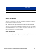
Table 2-1. I/O Ports
Port Function Description
Number of Ports
740wl 760wl 720wl
Network Uplink RJ45, 10Base-T/
100Base-TX/1000Base-T
1 1 1
Reserved port
(for future use)
RJ45, 10Base-T/
100Base-TX/1000Base-T
1 1 1
Serial Console DB9, Serial Port 1 1 1
Access Controller Downlink
Port
RJ45, 10Base-T/100Base-TX 0 up to 12 up to 12
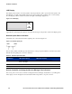
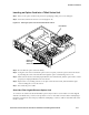
Controls and Indicators
Controls
There is only one control on the front of the chassis, a power button, labeled I/0. The power button is a
momentary switch and is used to turn on the system.
Note: The front panel power button should not be used to power off the system. Turning off the
system should be performed through software.
There is also a power switch on the rear of the 700wl Series chassis, next to the power cord socket. This
switch must be left in the On (
I) position for the unit to be operational, and cannot be used to power on
the system. When this switch is in the Off (0) position, the front panel power button will not function.
700wl Series units do not have a power switch on the back.
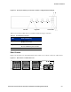
System Status Indicators
There are two system status LED indicators on the front of the chassis—Power (ON) and HDD.
• ON is lit when the power supply is plugged in to a live outlet, the rear panel On/Off switch is in the
On position, and the power is turned on by the front panel On/Off button.
• HDD is lit when the internal hard disk drive is in use.
HP ProCurve Secure Access 700wl Series Installation and Getting Started Guide 2-5