
Installation and Getting Started Guide for 720wl/740wl/760wl 2004-03


Hardware Installation
LCD Display
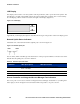
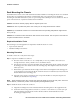
The display can be used to view the system’s network parameters, and to power down the system. The
LCD display is located in the middle of the front panel of 700wl Series products. It is a 16 character by
two line display, with two buttons located to the right of the display (
Figure 2-8).
Figure 2-8. LCD Display
SCROLL
SELECT
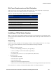
Appendix B, “LCD Display Description” describes the messages and operation of the LCD display panel.
Network Uplink Status Indicators
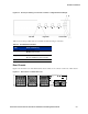
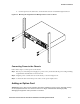
A detailed view of the network interface (uplink port) is shown in Figure 2-9.
Figure 2-9. Network Uplink port
LED1 LED2
The two LEDs, LED1 and LED2, provide information on the port speed and data connection state of the
default network uplink port as shown in Table 2-2.
Table 2-2. Network uplink LED status
LED State LED1 (Port Speed) LED2 (Connection)
On Orange: 100 Mbps
Green: 1000 Mbps
Link established, Good connection
Off 10 Mbps No link/no connection
Blinking –– Transferring data
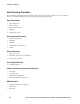
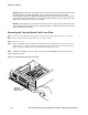
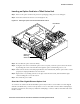
Access Controller and Integrated Access Manager Port Indicators
The access ports on an Access Controller or Integrated Access Manager are labeled 1 to 4, reading from
left to right, as shown in
Figure 2-10. Each Cluster LED corresponds to one port as shown.
2-6 HP ProCurve Secure Access 700wl Series Installation and Getting Started Guide