
Installation and Getting Started Guide for 720wl/740wl/760wl 2004-03


Hardware Installation
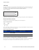
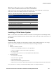
Figure 2-10. Access port labeling on an Access Controller or Integrated Access Manager
Left LED Right LED
1
11
1
22
2
33
3
44
4
Cluster LEDs
2 3 4
Table 2-3 shows the possible states for each LED and the meaning of each state.
Table 2-3. Port LED Status Indicators
LED State and Meaning
Left LED Off: No activity
Blinking: Data transfer
Right LED Off: No link/no connection
On: Link established, good connection
Cluster LEDs Not used
Rear Chassis
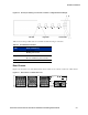
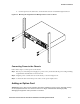
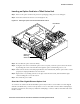
Figure 2-11 shows the rear of the 700wl Series chassis. There are no controls on the rear of this chassis.
Figure 2-11. Rear chassis of a 700wl Series unit
Access Controller
ASSEMBLED IN THE U.S.A.
SN
20000000
B1
7-700-210
720wl
Wide-Ranging
Input
100-240V
6A
50/60Hz
C
U
L
R
LISTED
E221805
I.T.E.
US
HP ProCurve Secure Access 700wl Series Installation and Getting Started Guide 2-7