
Installation and Getting Started Guide for 720wl/740wl/760wl 2004-03

Hardware Installation
Warning: Blank option card cover plates and cover panels serve three important functions: they
prevent exposure to hazardous voltages and currents inside the chassis; they contain
electromagnetic interference (EMI) that might disrupt other equipment; and they direct the flow
of cooling air through the chassis. Do not operate the system unless all cards, option card cover
plates, front covers, and rear covers are in place.
Warning: High Voltages are present! Do not remove the cover until all power cables have been
disconnected and the chassis is properly grounded. Failure to observe this may result in severe
injury or death by electrocution.
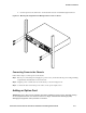
Removing the Top and Option Card Cover Plate
Step 1. Be sure that all cables have been removed, and attach a proper ESD wrist strap to your wrist.
Step 2. Remove eight screws that secure the top cover to the chassis.
Step 3. Remove the cover.
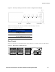
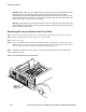
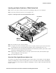
Step 4. Using a #2 Phillips-head screwdriver inserted through the appropriate hole on the option card
retaining screw cover, remove the screw holding the option card cover plate. Remove the option
card cover plate from the front of the 700wl Series system (
Figure 2-13).
Note: A magnetic screwdriver may be useful, to help avoid screws falling into the unit, where they
may be difficult to retrieve.
Figure 2-13. Removing the option card cover plate
3
4
1
2
S
C
R
O
L
L
S
ELECT
NE
T
WO
R
K
U
P
LIN
K
RE
SERVED
1
2
3
Option card
Retaining
Screw Cover
2-12 HP ProCurve Secure Access 700wl Series Installation and Getting Started Guide