Configuration Guide 5991-3823 December 2005 Configuring T1 and E1 WAN Interfaces This configuration guide explains the processes for configuring your Secure Router Operating System (SROS) T1/E1 product for some common applications. This guide discusses configuring the T1/E1 interfaces, various Layer 2 (L2) protocols, many-to-one Network Address Translation (NAT), and adding static routes to the route table.
Overview of T1/E1 WAN Applications Understanding SROS Queuing Methods Overview of T1/E1 WAN Applications Wide area networks (WANs) provide the mechanism for connecting remote sites together and connecting your local network to the Internet through a connection to an ISP. WANs use a variety of physical transports; T1/E1 connections are a common means of transport.T1 circuits are generally used in domestic applications, while E1 circuits are widely deployed internationally.
Understanding SROS Queuing Methods Physical Interface Configurations (T1, E1, and Ethernet) Physical Interface Configurations (T1, E1, and Ethernet) Note Interface Modules use a slot/port notation for interface identification (e.g., t1 1/1). All non-modular interfaces built into the base unit are identified using 0 as the slot number (e.g. eth 0/1). To begin configuring physical interfaces, you must first activate the appropriate interface configuration mode from the Global configuration prompt.
Configuring Ethernet Interfaces Understanding SROS Queuing Methods Configuring Ethernet Interfaces Ethernet interface configuration can range from assigning an IP address and activating the interface to activating the DHCP client to poll the network DHCP server to gain an IP address. Standard Ethernet configurations generally contain an IP address, a speed, and a duplex setting.
Understanding SROS Queuing Methods Configuring Ethernet Interfaces Configuring T1 Interfaces There are four main settings to consider when configuring T1 network interfaces. The line coding (coding), framing format (framing), active channels (tdm-group), and clock source (clock source) must all be configured to match the circuit supplied by your network provider.
Configuring Ethernet Interfaces Understanding SROS Queuing Methods Configuring E1 Interfaces There are four main settings to consider when configuring E1 network interfaces. The line coding (coding), framing format (framing), active channels (tdm-group), and clock source (clock source) must all be configured to match the circuit supplied by your network provider.
Understanding SROS Queuing Methods Configuring Layer 2 Protocols (Frame Relay, PPP, HDLC) Configuring Layer 2 Protocols (Frame Relay, PPP, HDLC) Each WAN connection in your SROS product must contain a physical interface (T1, E1, ADSL, etc.) and a Layer 2 protocol (ATM, Frame Relay/multilink Frame Relay, PPP/multilink PPP, or HDLC). The physical interface provides the actual bandwidth between your device and the network provider.
Configuring the Frame Relay Interfaces (and Sub-Interfaces) Understanding SROS Queuing Methods The following commands specify the configuration parameters required for a standard Frame Relay sub-interfaces: ProCurve(config)#interface fr 2.16 ProCurve(config-fr 2.16)#frame-relay interface-dlci 16 ProCurve(config-fr 2.16)#frame-relay bc 768000 ProCurve(config-fr 2.16)#frame-relay be 768000 ProCurve(config-fr 2.16)#ip address 192.168.72.1 /30 ProCurve(config-fr 2.16)#no shutdown ProCurve(config-fr 2.
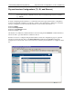
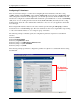
Understanding SROS Queuing Methods Configuring the Frame Relay Interfaces (and Sub-Interfaces) After clicking Apply, the Frame Relay configuration page displays: Click the Add button (in the Permanent Virtual Circuits section) to create a new Frame Relay sub-interface.
Configuring the Frame Relay Interfaces (and Sub-Interfaces) Understanding SROS Queuing Methods Specify the Frame Relay sub-interface configuration parameters on the DLCI Configuration page: Click Apply to create the Frame Relay sub-interface. Multilink Frame Relay Operation Multilink Frame Relay operation increases bandwidth on your Frame Relay service by aggregating multiple physical links into a single logical bundle.
Understanding SROS Queuing Methods Configuring the Frame Relay Interfaces (and Sub-Interfaces) the bundle), but SROS will automatically define one based on the specified Frame Relay interface. For example, if multilink operation is enabled on a Frame Relay interface labeled fr 1, the bundle ID becomes mfr1 (with the 1 corresponding to the label of the Frame Relay interface). Bundle IDs can be character strings containing 1 to 48 characters.
Configuring PPP Interfaces Understanding SROS Queuing Methods Configuring PPP Interfaces There are two settings to consider when configuring PPP interfaces: the IP address and the maximum transmission unit (MTU). There are no default IP addresses, so each interface must be manually programmed with the appropriate address (ip address). All SROS router PPP interfaces have a default MTU of 1500 bytes, which works for most applications.
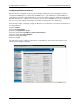
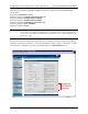
Understanding SROS Queuing Methods Configuring PPP Interfaces After clicking Apply, the PPP configuration page displays: Specify the IP address parameters at the bottom of the page: Click Apply to create the PPP interface.
Configuring PPP Interfaces Understanding SROS Queuing Methods Multilink PPP Operation Multilink PPP operation increases bandwidth on your PPP connection by aggregating multiple physical links into a single logical bundle. All the physical links in a multilink bundle are treated as a single entity by the system, allowing each PPP session on the connection to dynamically share the total bandwidth of the bundle.
Understanding SROS Queuing Methods Configuring HDLC Interfaces and select the interface from the drop down list. Multilink L2 Interface Drop Down List Configuring HDLC Interfaces HDLC is a protocol developed by the International Organization for Standardization (ISO) under standards ISO 3309 and 4335. Originally created for the mainframe environment, HDLC has become popularly used in many network environments because of its flexibility and ease of configuration.
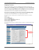
Configuring HDLC Interfaces Understanding SROS Queuing Methods L2 protocol interfaces are created in the Web GUI on the configuration page for the physical interface to which they are bound. For example, to create the HDLC interface to bind to a T1 interface, activate the T1 interface configuration page and specify HDLC in the Encapsulation section: Create the L2 Protocol Interface After clicking Apply, the HDLC configuration page displays.
Understanding SROS Queuing Methods Binding Physical and Virtual Interfaces Binding Physical and Virtual Interfaces Virtual interfaces must be bound to physical interfaces to create a WAN interface where L2 signaling occurs. Use the bind command to connect the physical and virtual interfaces. A single virtual interface is assigned to a single physical interface, except in the case of multilink operation, where one virtual interface is connected with multiple physical interfaces.
Access Policy Action Statements Understanding SROS Queuing Methods The following outlines the syntax for creating a standard ACL entry: permit | deny Select the traffic into the list using the permit keyword, or block the traffic from the list using the deny keyword. The source IP addresses can be entered in one of three ways: 1. Using the keyword any to match any IP address.
Understanding SROS Queuing Methods Access Policy Action Statements allow list All packets permitted by the access list(s) will be allowed to enter the router system. allow list policy All packets permitted by the access list(s) and destined for the interface using the access policy listed will be allowed to enter the router system. This command creates configurations to allow packets to a single interface and not the entire system.
Access List and Access Policy Example Understanding SROS Queuing Methods nat source list address overload policy All packets permitted by the access list(s) will be modified to replace the source IP address with the entered IP address. The overload keyword allows multiple source IP addresses to be replaced with the single IP address entered. This hides private IP addresses from outside the local network.
Understanding SROS Queuing Methods Access List and Access Policy Example Begin by planning the ACL selectors for the traffic received on the connection to the branch office. Use extended ACLs to use source and destination IP addresses to sort the traffic received from the remote LANs into two categories – traffic destined for the corporate LAN or traffic destined for the public Internet. Each category requires an extended ACL to select the appropriate traffic.
Configuring Routing Information (Static Routes) Understanding SROS Queuing Methods Now, create the access policy to allow the traffic between the LANs and to NAT traffic bound for the public Internet. ProCurve(config)#ip policy-class INTERLANwNAT ProCurve(config-policy-class)#allow list INTERLAN ProCurve(config-policy-class)#nat source list INTERNET interface ppp 1 overload ProCurve(config-policy-class)#exit ProCurve(config)# Apply the ACPs to the interface(s) to complete the configuration.
Understanding SROS Queuing Methods Static Route Example Static Route Example Let’s review the following example to illustrate the static route creation process. 10.25.15.0/24 10.10.4.0/24 ProCurve Secure Router 7203dl ProCurve Secure Router 7102dl 68.22.15.2/30 68.22.15.1/30 (ISP Router) Internet PPP The following table outlines the static routes needed in the Corporate HQ router. Destination Address Subnet Mask Next-Hop Address/Forwarding Interface 10.10.10.0 255.255.255.0 fr 1.
Configuration Examples Understanding SROS Queuing Methods Configuration Examples This guide contains four examples for basic WAN applications. • Frame relay/multilink Frame Relay between sites • PPP/multilink PPP in a point-to-point scenario between sites • PPP/multilink PPP for a public connection to an ISP • HDLC for a public connection to an ISP Each example provides a network diagram, configuration parameters (to explain complicated network diagrams), and the sample script.
Understanding SROS Queuing Methods Frame Relay/Multilink Frame Relay Application Example Configuration Script ! ! hostname "Corporate HQ" enable password md5 encrypted 7f1a02ddd2cf3df129eb99c8408a5e28 ! ! ip firewall no ip firewall alg h323 ip firewall alg sip ! ! interface eth 0/1 ip address 10.10.0.7 255.255.255.
Frame Relay/Multilink Frame Relay Application Understanding SROS Queuing Methods ip address 192.168.72.5 255.255.255.252 ! interface fr 1.18 point-to-point frame-relay interface-dlci 18 frame-relay bc 768000 frame-relay be 768000 ip address 192.168.72.9 255.255.255.252 ! interface ppp 1 ip address 68.22.15.2 255.255.255.252 no shutdown bind 4 t1 3/8 1 ppp 1 ! ! ip access-list extended InterLAN permit ip 10.10.0.0 0.0.255.255 10.10.0.0 0.0.255.255 ! ip access-list extended INTERNET permit ip 10.10.0.0 0.0.
Understanding SROS Queuing Methods PPP/Multilink PPP (Point-to-Point) Example PPP/Multilink PPP (Point-to-Point) Example Customer Site A Customer Site B 1 to 8 T1s/E1s T1/E1 PPP (Multilink Optional) 10.10.10.1/24 192.168.72.1/30 192.168.72.2/30 10.10.20.1/24 Example Configuration Script ! ! hostname "Customer Site A" enable password md5 encrypted 7f1a02ddd2cf3df129eb99c8408a5e28 ! ! ip firewall no ip firewall alg h323 ip firewall alg sip ! interface eth 0/1 ip address 10.10.10.1 255.255.255.
PPP/Multilink PPP (Point-to-Point) Example Understanding SROS Queuing Methods ! ! ! ip access-list extended INTERLAN permit ip 10.10.20.0 0.0.0.255 10.10.10.0 0.0.0.255 ! ip policy-class INTERLAN allow list INTERLAN ! ! ip route 10.10.20.0 255.255.255.
Understanding SROS Queuing Methods PPP/Multilink PPP (Public Internet) Example PPP/Multilink PPP (Public Internet) Example Internet Service Provider (ISP) Customer Site 1 to 8 T1s/E1s Internet T1/E1 PPP (Multilink Optional) 10.10.10.1/24 172.16.1.2/30 172.16.1.1/30 Example Configuration Script ! ! hostname "Customer Site" enable password md5 encrypted 7f1a02ddd2cf3df129eb99c8408a5e28 ! ! ip firewall no ip firewall alg h323 ip firewall alg sip ! ! ! interface eth 0/1 ip address 10.10.10.1 255.255.
PPP/Multilink PPP (Public Internet) Example interface ppp 1 ip address 172.16.1.2 255.255.255.252 ppp multilink no shutdown bind 1 t1 3/1 1 ppp 1 bind 2 t1 3/2 1 ppp 1 bind 3 t1 3/3 1 ppp 1 ! ! ! ip access-list extended MATCHALL permit ip any any ! ip policy-class NAT nat source list MATCHALL interface ppp 1 overload ! ! end 30 Understanding SROS Queuing Methods Enables multilink PPP on the interface. For regular PPP applications, remove this statement. Multiple binds for multilink PPP.
Understanding SROS Queuing Methods HDLC (Public Internet) Example HDLC (Public Internet) Example Internet Service Provider (ISP) Customer Site Internet T1/E1 HDLC 10.10.10.1/24 172.16.1.2/30 172.16.1.1/30 Example Configuration Script ! ! hostname "Customer Site" enable password md5 encrypted 7f1a02ddd2cf3df129eb99c8408a5e28 ! ! ip firewall no ip firewall alg h323 ip firewall alg sip ! interface eth 0/1 ip address 10.10.10.1 255.255.255.