ProCurve Secure Router (with 8xT1/E1 Wide Module) Quick Configuration Guide 5991-2118 April 2005 Equipment Required • A VT100 terminal or a PC with VT100 emulator software for connecting to the unit. • Serial cable (5184-1894) supplied with the router. This console cable is used in other ProCurve switches such as the 5300xl series. The console port is a DB-9 DTE male connector. • Appropriate cable(s) for connecting the system to the existing network.
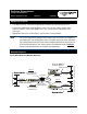
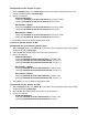
Network Diagrams (continued) PPP Diagram (Multilink Optional) 1 eth 0/1 LAN IP: 10.10.20.7 /24 2 to 8 T1s/E1s T1/E1 PPP (Multilink Optional) T1/E1 68.168.72.2 /24 T1/E1 68.168.72.3 /24 LAN IP:10.10.30.1 /24 2 Network IP: 10.10.30.0 Network IP: 10.10.20.0 /24 PPP1 ML PPP Signaling 68.168.72.1 /24 Network IP: 10.10.10.0 LAN IP:10.10.10.1 /24 Configure the Unit The ProCurve Secure Router may be initially accessed and managed via a console session.
Configure the Ethernet Port Parameters 1. At the (config)# prompt, enter interface eth 0/1 to access the configuration parameters for the Ethernet port located on the base unit. 2. Enter ip address 10.10.20.7 255.255.255.0 to assign an IP address to the Ethernet port using a 24-bit subnet mask. Note If you are accessing the ProCurve Secure Router via Telnet, once you change this IP address, you will lose connection to the router. You must change the IP address of your PC before you can proceed.
Create the T1 Interface TDM Group The following steps demonstrate configuring a T1 network interface with all timeslots (1 through 24) reserved for data. 1. At the (config-t1 3/1)# prompt, enter tdm-group 1 timeslots 1-24 to create a TDM group for DS0s 1 through 24 on the T1 network connection (t1 3/1). 2. Enter no shutdown to activate the T1 interface. 3. Enter exit to return to the Global Configuration mode.
Configure the Frame Relay Virtual Interface The following steps outline configuring a Frame Relay virtual interface (labeled 1) using a single DLCI back to the corporate router (defined as DLCI 16). Skip to Configure the PPP Interface on page 6 if you are using PPP. 1. At the (config)# prompt, enter interface fr 1 to create a Frame Relay virtual interface labeled 1. 2.
Configure the PPP Interface The following steps show how to configure a PPP virtual interface (labeled 1) to the corporate router. Skip to Bind the Interfaces if you are using Frame Relay. 1. At the (config)# prompt, enter interface ppp 1 to create a PPP virtual interface labeled 1. Note If your application requires multilink PPP functionality, complete step 2 to enable multilink on the PPP interface. If multilink is not required, skip to step 3. 2. Enter ppp multilink to enable the multilink interface.
Configure Static Routes Routes may be assigned either statically or dynamically. Continue with this section to create a static route. Refer to Configure Dynamic Routes on page 8 for information on configuring RIP and OSPF dynamic route assignments. Note These examples are based on the network diagrams on pages 1 and 2. Depending on your network setup, configure static routing on your unit in one of the following ways. Configuration for Corporate HQ router in the diagram on page 1 (Frame Relay) 1.
Configuration for Branch Office 2 router in the diagram on page 1 (Frame Relay) 1. At the (config)# prompt, enter ip route 0.0.0.0 0.0.0.0 frame-relay 1.19 to set up the default route to the Corporate HQ. 2. The internet router at the far side (Corporate HQ) will need a route statement to send traffic back to this network through the ProCurve Secure Router. The information (based on the diagram shown at the beginning of this document) is as follows: • Destination address: 10.10.30.
Configuration for PPP diagram on page 2 1. At the (config)# prompt, enter router ospf to activate the OSPF configuration mode. Your prompt should now display (config-ospf)#. 2. Specify the networks: Corporate HQ Router (config-ospf)#network 10.10.20.0 0.0.0.255 area 0 (for eth 0/1 LAN) (config-ospf)#network 68.168.72.0 0.0.0.255 area 0 (for PPP 1) Branch Office 1 Router (config-ospf)#network 10.10.10.0 0.0.0.255 area 0 (for eth 0/1 LAN) (config-ospf)#network 68.168.72.0 0.0.0.
Branch Office 1 Router (config-rip)#network 10.10.10.0 255.255.255.0 (for eth 0/1) (config-rip)#network 68.168.72.0 255.255.255.0 (for PPP 1) Branch Office 2 Router (config-rip)#network 10.10.30.0 255.255.255.0 (for eth 0/1) (config-rip)#network 68.168.72.4 255.255.255.252 (for PPP 1) 4. Enter exit to return to the Global Configuration mode. Set Enable Security Mode Password 1. Verify that the prompt of your unit displays (config)#. 2. Enter enable password word to set the Enable Security mode password.
Complete the Installation The ProCurve Secure Router is now configured and operational. Complete the installation by connecting the appropriate cables to the T1 and Ethernet networks. Please refer to the ProCurve Secure Router Installation Guide for more details on pinouts and cabling. Script for this Example Note The scripts below contains ALL configuration parameters for each part of this example and cannot be used in their entirety. Each section is divided by a row of symbols (*).
! Create a TDM group (labeled 1) on the T1 interface containing ! all 24 DS0s (1-24). tdm group 1 timeslots 1-24 ! ! Activate the interface. no shutdown ! ! Exit back to the global configuration mode. exit ! ! 2ND T1 INTERFACE CONFIGURATION !************************************************************************! ! Enter the interface configuration mode for the second T1 ! interface. interface t1 3/2 ! ! Configure the t1 interface to recover clocking from the T1 ! network connection.
! 2ND E1 INTERFACE CONFIGURATION !************************************************************************! ! Enter the interface configuration mode for the second E1 ! interface. interface e1 3/2 ! ! Configure the e1 interface to recover clocking from the E1 ! network connection. clock source line ! ! Enable CRC-4 framing on the interface framing crc4 ! ! Create a tdm group (labeled 1) on the E1 interface containing ! timeslots 1 through 31 (1-31). tdm group 1 timeslots 1-31 ! ! Activate the interface.
! Now assign DLCI 16 to the pvc. frame-relay interface-dlci 16 ! ! Next, assign an IP address to this pvc. ip address 192.168.72.1 255.255.255.252 ! ! Activate the interface. no shutdown ! ! Exit back to the global configuration mode. exit ! interface fr 1.17 ! ! Your prompt should now display Router(config-fr1.17)#. ! ! Now assign DLCI 17 to the pvc. frame-relay interface-dlci 17 ! ! Next, assign an IP address to this pvc. ip address 192.168.72.5 255.255.255.252 ! ! Activate the interface.
! BINDING THE INTERFACES - FRAME RELAY !*************************************************************! ! Connect the tdm group (1) on the first t1 interface to the ! virtual multilink Frame Relay interface (fr 1). ! bind 1 t1 1/1 1 frame-relay 1 ! ! (Multilink Only) Connect the tdm group (1) on the second t1 interface to the ! virtual multilink Frame Relay interface (fr 1).
! CONFIGURING DYNAMIC ROUTES VIA OSPF - CORP HQ - FRAME RELAY !****************************************************************************************************! ! Enter the OSPF configuration mode. router ospf ! ! Your prompt should now display (config-ospf)#. ! ! Specify the networks. network 10.10.20.0 0.0.0.255 area 0 network 192.168.72.0 0.0.0.3 area 0 network 192.168.72.4 0.0.0.4 area 0 ! ! Exit back to the global configuration mode.
! ! Define RIP version 2. version 2 ! ! Specify the networks. network 10.10.20.0 255.255.255.0 network 68.168.72.0 255.255.255.0 ! ! Exit back to the global configuration mode. exit ! ! ENABLE THE SECURITY MODE PASSWORD !*************************************************************! ! Activate the enable password.
!***********************************************************************************************************! ! Branch Office Router Script !***********************************************************************************************************! ! This is a sample script to configure the 8xT1/E1 Wide Module for the Branch ! Office 1 Router in the diagrams on page 1 and page 2. The following script can be ! used for the Branch Office 2 Router configuration by changing the appropriate IP ! addresses.
! E1 INTERFACE CONFIGURATION !*************************************************************! ! Enter the E1 interface configuration mode. interface e1 1/1 ! ! Configure the e1 interface to recover clocking from the E1 ! network connection. clock source line ! ! Enable CRC-4 framing on the interface. framing crc4 ! ! Create a tdm group (labeled 1) on the E1 interface containing ! timeslots 1 through 31 (1-31). tdm group 1 timeslots 1-31 ! ! Activate the interface to pass data.
! ! Activate the interface. no shutdown ! ! Exit back to the global configuration mode. exit ! ! PPP VIRTUAL INTERFACE CONFIGURATION !****************************************************************************! ! Create a PPP virtual interface (labeled 1) and enter the ! PPP configuration mode. ! ! Your prompt should now display (config-ppp1)#. ! ! Assign an IP address to the interface using a 30-bit mask. ip address 68.168.72.2 255.255.255.252 ! ! Activate the interface.
! CONFIGURING DYNAMIC ROUTES VIA OSPF - BRANCH OFFICE 1 - FRAME RELAY !***********************************************************************************************************! ! Enter the OSPF configuration mode. router ospf ! ! Your prompt should now display (config-ospf)#. ! ! Specify the networks. network 10.10.10.0 0.0.0.255 area 0 network 192.168.72.0 0.0.0.3 area 0 ! ! Exit back to the global configuration mode.
! Define RIP version 2. version 2 ! ! Specify the networks. network 10.10.10.0 255.255.255.0 network 68.168.72.0 255.255.255.0 ! ! Exit back to the global configuration mode. exit ! ! ENABLE THE SECURITY MODE PASSWORD !*************************************************************! ! Activate the enable password.