Installation and Getting Started Guide HP ProCurve Series 6600 Switches www.procurve.
ProCurve Series 6600 Switches Installation and Getting Started Guide
© Copyright 2009 Hewlett-Packard Development Company, L.P. Disclaimer HEWLETT-PACKARD COMPANY MAKES NO WARRANTY OF ANY KIND WITH REGARD TO THIS MATERIAL, INCLUDING, BUT NOT LIMITED TO, THE IMPLIED WARRANTIES OF MERCHANTABILITY AND FITNESS FOR A PARTICULAR PURPOSE. Hewlett-Packard shall not be liable for errors contained herein or for incidental or consequential damages in connection with the furnishing, performance, or use of this material.
Contents 1 Introducing the Switch Front of the Switch . . . . . . . . . . . . . . . . . . . . . . . . . . . . . . . . . . . . . . . . . . . . . . 1-4 Network Ports . . . . . . . . . . . . . . . . . . . . . . . . . . . . . . . . . . . . . . . . . . . . . . 1-5 LEDs . . . . . . . . . . . . . . . . . . . . . . . . . . . . . . . . . . . . . . . . . . . . . . . . . . . . . . 1-6 LED Power Save Mode . . . . . . . . . . . . . . . . . . . . . . . . . . . . . . . . . . .
7. Connect the Network Cables . . . . . . . . . . . . . . . . . . . . . . . . . . . . . . . 2-18 Using the RJ-45 Connectors . . . . . . . . . . . . . . . . . . . . . . . . . . . . . . 2-18 Connecting Cables to mini-GBICs . . . . . . . . . . . . . . . . . . . . . . . . . 2-18 8. (Optional) Connect a Console to the Switch . . . . . . . . . . . . . . . . . . Terminal Configuration . . . . . . . . . . . . . . . . . . . . . . . . . . . . . . . . . . Direct Console Access . . . . . . . . . . . . . . . . . . . . .
Testing End-to-End Network Communications . . . . . . . . . . . . . . . . . 5-10 Restoring the Factory Default Configuration . . . . . . . . . . . . . . . . . . . . . . . 5-11 Downloading New Switch Software . . . . . . . . . . . . . . . . . . . . . . . . . . . . . . 5-12 HP Customer Support Services . . . . . . . . . . . . . . . . . . . . . . . . . . . . . . . . . . 5-12 Before Calling Support . . . . . . . . . . . . . . . . . . . . . . . . . . . . . . . . . . . . . . 5-12 A Specifications Physical . . .
C Safety and EMC Regulatory Statements Safety Information . . . . . . . . . . . . . . . . . . . . . . . . . . . . . . . . . . . . . . . . . . . . . C-1 Informations concernant la sécurité . . . . . . . . . . . . . . . . . . . . . . . . . . . . . . C-2 Hinweise zur Sicherheit . . . . . . . . . . . . . . . . . . . . . . . . . . . . . . . . . . . . . . . . . C-3 Considerazioni sulla sicurezza . . . . . . . . . . . . . . . . . . . . . . . . . . . . . . . . . . . C-4 Consideraciones sobre seguridad . . . . . . .
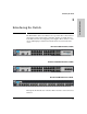
Introducing the Switch Introducing the Switch The HP ProCurve Series 6600 Switches are top-of-rack data center switches that support advanced Layer three switching, and have reversible front-toback airflow, and two hot-swappable power supplies. These switches can be used to build high-speed switched networks between servers in the data center.
Introducing the Switch Introducing the Switch The 6600-24G Switch has 20 auto-sensing 10/100/1000Base-T RJ-45 ports, four dual-personality ports—either auto-sensing 10/100/1000Base-T RJ-45 or miniGBIC (Small Form-Factor Pluggable (SFP)) ports. The 6600-24G-4XG Switch has the same ports as the Switch 6600-24G plus it also has 4 SFP+ slots for 10-GbE connectivity. The specification for SFP+ defines the physical and electrical characteristics of this form-factor (size and shape).
Introducing the Switch This chapter describes the Series 6600 Switches, including: ■ ■ ■ ■ Front and back of the switches Network ports LEDs Switch features 1-3 Introducing the Switch These switches are designed to be used primarily in data center environments mounted in equipment racks along with the servers they are connected to.
Introducing the Switch Front of the Switch Introducing the Switch Front of the Switch Power, Fault, and Locator LEDs PS, Tmp, Fan, and Test Status LEDs Auxiliary port and LED Console port Port LED Mode select button and indicator LEDs 10/100/1000Base-T RJ-45 ports Reset and Clear buttons Switch port LEDs Link and Mode Dual-personality ports (1000Base-T or mini-GBIC) Figure 1-1.
Introducing the Switch Front of the Switch Console port Introducing the Switch Power, Fault, and locator LEDs PS, Tmp, Fan, and Test Status LEDs Out of Band Management port, for future use Auxiliary port and LED Link and Mode LEDs Port LED Mode select button and indicator LEDs SFP+ 10-GbE ports Reset and Clear buttons Figure 1-3. ProCurve 6600-24XG Switch Network Ports ■ On the 6600-24G and 6600-24G-4XG Switches there are 24 auto-sensing 10/100/1000Base-T ports.
Introducing the Switch Front of the Switch Introducing the Switch LEDs Table 1-2. Switch LEDs Switch LEDs State Meaning Power (green) On Blinking1 Off The power supply is operating properly. Power supply failure. Blinking simultaneously with Fault LED No power connection. Fault (orange) Off The normal state; indicates there are no fault conditions on the switch. Blinking1 A fault has occurred on the switch, one of the switch ports, module in the rear of the switch, or the fan.
Introducing the Switch Front of the Switch State Meaning Test (green/orange) Off The normal operational state; the switch is not undergoing self test. On green The switch self test and initialization are in progress after the switch has been power cycled or reset. The switch is not operational until this LED goes off. The Self Test LED also comes on briefly when you “hot swap” a mini-GBIC into the switch; the mini-GBIC is self tested when it is hot swapped.
Introducing the Switch Front of the Switch Introducing the Switch Switch LEDs 1 2 State Meaning The Blinking behavior is an on/off cycle once every 1.6 seconds, approximately. The Blinking behavior is an on/off cycle once every 0.8 seconds, approximately. LED Power Save Mode The HP ProCurve 6600-24XG Switch (J9265A) has the ability to turn off defined groups of ports to save power through the use of a CLI command, “savepower”.
Introducing the Switch Front of the Switch Introducing the Switch Port LEDs Link and Mode LED Mode select button and indicator LED Figure 1-5. ProCurve 6600-24XG Switch ■ Each port has a Link LED. If it is lit, the port has a link. If the Link LED is Blinking, the port has failed its self test. The Fault and Self Test LEDs will be Blinking simultaneously.
Introducing the Switch Front of the Switch Introducing the Switch Clear Button This button is used for: ■ Deleting Passwords - When pressed by itself for at least one second, the button deletes any switch console access passwords that you may have configured. Use this feature if you have misplaced the password and need console access.
Introducing the Switch Back of the Switch Introducing the Switch Back of the Switch Power supply and Locator LEDs Power supply AC power connector Fan tray assembly Extra power slot Figure 1-6. HP ProCurve Series 6600 Switches. The backs of all these switches are the same. Power Connector The Series 6600 Switches do not have a power switch; they are powered on when connected to an active AC power source.
Introducing the Switch Introducing the Switch Switch Features 1-12 ■ The 6600-24G and the 6600-24G-4XG supports IEEE 802.3ab Auto MDIX on all 10/100/1000 twisted-pair ports, meaning that all connections can be made using straight-through twisted-pair cables. Cross-over cables are not required, although they will also work.
Installing the Switch Included Parts 2 Installing the Switch Caution If the switch is to be shipped in a rack, be sure to use only an HP 10K rack. Mount the switch using rail mounting kit, (5070-6532). The switch warranty may be voided.
Installing the Switch Included Parts Installing the Switch ■ Power cord, one of the following: Australia/New Zealand China Continental Europe Denmark Japan Switzerland United Kingdom/Hong Kong/Singapore United States/Canada/Mexico South Africa India Argentina Thailand Brazil Chile Taiwan Israel Japan Power Cord Warning 2-2 8120-6810 8120-8707 8120-6811 8120-6814 8120-4753 8120-6815 8120-6809 8120-6812 8120-6813 8120-6813 8120-6869 8121-0668 8121-1069 8120-6980 8121-0974 8121-1035
Installing the Switch Included Parts Installation Precautions: Follow these precautions when installing the Series 6600 Switches. WARNING The rack or cabinet should be adequately secured to prevent it from becoming unstable and/or falling over. ■ Devices installed in a rack or cabinet should be mounted as low as possible, with the heaviest devices at the bottom and progressively lighter devices installed above. ■ Do not wall mount the Series 6600 Switches.
Installing the Switch Installing the Switch Installation Procedures Figure 2-1. Default air flow direction of the Series 6600 Switches is from power to ports. The direction of air flow can be reversed from the default direction shown in figure 2-1 by reversing the direction of the fans. See step 3 below, Reversing the air flow. Installation Procedures Summary 2-4 1. Prepare the installation site (page 2-5).
Installing the Switch Installation Procedures Connect power to the switch (page 2-14). Once the switch is mounted, plug it into the nearby main power source. 6. (Optional) Install or remove mini-GBICs or SFPs (page 2-15). The switch has four slots for installing mini-GBICs. Depending on where you will mount the switch, it may be easier to install the mini-GBICs first. MiniGBICs can be installed or removed while the switch is powered on. 7. Connect the network cables (page 2-18).
Installing the Switch Installation Procedures Installing the Switch 1. Connect the power cord supplied with the switch to the power connector on the back of the power supply, and then into a properly grounded electrical outlet. Figure 2-2. Connecting the power cord. Note The Series 6600 Switches do not have a power switch. They are powered on when the power cord is connected to the power supply and to a power source. For safety, the power outlet should be located near the switch installation.
Installing the Switch Installation Procedures Switch port LEDs Power and Fault LEDs Test LED Figure 2-3. Checking the LEDs on the 6600-24G and 6600-24G-4XG Installing the Switch Switch port LEDs Power and Fault LEDs Test LED Figure 2-4. Checking the LEDs on the 6600-24XG LED Behavior: During the self test: • Initially, all the status, LED Mode and port LEDs are on for most of the duration of the test. • Most of the LEDs go off and then may come on again during phases of the self test.
Installing the Switch Installation Procedures – – If the ports are connected to active network devices, the LEDs behave according to the LED Mode selected. In the default view mode (Link), the LEDs should be on. If the ports are not connected to active network devices, the LEDs will stay off. If the LED display is different than what is described above, especially if the Fault and Test LEDs stay on for more than 60 seconds or they start blinking, the self test has not completed correctly.
Installing the Switch Installation Procedures 3. Lift the fan assembly from the fan tray high enough to turn it over. Retaining Screw Rotate the fan assembly 180 degrees and replace the fan assembly into the fan tray, sheet metal side up. Rotated position 5. Take care to align the sensing pin between the two sensors and replace the 4 retaining screws. Sensors Sensing pin 6. Replace the fan tray assembly into the switch. 7. Tighten the retaining screws.
Installing the Switch Installation Procedures 4. Mount the Switch After the switch passes self test, it is ready to be mounted in a stable location. Rack or Cabinet Mounting Installing the Switch The Series 6600 Switches are designed to be mounted in any EIA-standard 19inch telco rack or communication equipment cabinet using the balanced or center mounting orientation, see figure 2-5. Flush mounting in a two post rack is not supported.
Installing the Switch Installation Procedures 1. Use a #1 Phillips (cross-head) screwdriver and attach the mounting brackets to the switch with the included 8-mm M4 screws. Remember to use the correct accessory kit for your switch, see page 2-1. 8 mm M4 screws Figure 2-6. Example attaching mounting brackets 2-11 Installing the Switch Figure 2-5. Mounting in a two post rack using the balanced option.
Installing the Switch Installation Procedures Installing the Switch 2. Attach the holding brackets. Ensure the holes of the brackets and the screws are aligned to the bottom of the switch. Figure 2-7. Installing the rail mounting holding brackets 3. Install the rails. Figure 2-8.
Installing the Switch Installation Procedures 4. Slide the switch into the rails 5. Hold the switch with attached brackets up to the rack and move it vertically until rack holes line up with the bracket holes, then insert and tighten the four number 12-24 screws holding the brackets to the rack. Figure 2-10. Mounting in a rack Caution Make sure the air flow is not restricted in the front or back of the switch. See Figure 2-1 on page 2-4 for the air flow direction.
Installing the Switch Installation Procedures 5. Connect the Switch to a Power Source 1. Plug the included power cord into the switch’s power connector and into a nearby AC power source. 2. Re-check the LEDs during self test. See “LED Behavior” on page 2-7. Securing the power cord 1.Connect the power cord to the power supply. Installing the Switch 2.Make a small loop in the power cord, approximately 3 to 4 inches and insert the velcro strap through the loop and through the handle on power supply. 3.
Installing the Switch Installation Procedures 3. 4. Installing the Switch 5. 6. (Optional) Install or Remove mini-GBICs or SFPs You can install or remove a mini-GBIC from a mini-GBIC slot without having to power off the switch. Use only ProCurve transceiver accessories. Notes ■ The mini-GBIC slots are shared with the four 10/100/1000Base-T RJ-45 ports. If a mini-GBIC is installed in a slot, the associated RJ-45 port is disabled and cannot be used. ■ The mini-GBICs operate only at full duplex.
Installing the Switch Installation Procedures Installing the Switch Note Direct attach cables (DAC) are lowcost 10-GbE connectivity options consisting of a one, three, or seven meter cable with SFP+ connectors permanently attached to each end. Figure 2-11. One meter DAC Caution Use only supported genuine HP ProCurve transceiver accessories with your switch. Non-ProCurve transceiver accessories are not supported, and their use may result in product malfunction.
Installing the Switch Installation Procedures WARNING The ProCurve mini-GBICs are Class 1 laser devices. Avoid direct eye exposure to the beam coming from the transmit port. SFP and SFP+ transceivers Plug-in, Fault and Alert behaviors. Working SFP Transceiver plugged into SFP slot 21S, 22S, 23S or 24S: ■ When the switch recognizes the transceiver, the Mode LED turns on solid for 2 seconds and then goes to normal operation.
Installing the Switch Installation Procedures To remove the mini-GBICs that have the plastic tab or plastic collar, push the tab or collar toward the switch until you see the mini-GBIC release from the switch (you can see it move outward slightly), and then pull it from the slot. To remove the mini-GBICs that have the wire bail, lower the bail until it is approximately horizontal, and then using the bail, pull the mini-GBIC from the slot. 7.
Installing the Switch Installation Procedures For mini-GBICs ports, and in general for all the switch ports, when a network cable from an active network device is connected to the port, the port LED for that port should go on. If the port LED does not go on when the network cable is connected to the port, see “Diagnosing with the LEDs” on page 5-4 in chapter 5, “Troubleshooting”. 8. (Optional) Connect a Console to the Switch Figure 2-14.
Installing the Switch Installation Procedures Terminal Configuration To connect a console to the switch, configure the PC terminal emulator as a DEC VT-100 (ANSI) terminal or use a VT-100 terminal, and configure either one to operate with these settings: ■ any baud rate from 1200 to 115200 (the switch senses the speed) ■ 8 data bits, 1 stop bit, no parity, and flow control set to Xon/Xoff ■ for the Windows Terminal program, also disable (uncheck) the “Use Function, Arrow, and Ctrl Keys for Windows” op
Installing the Switch Installation Procedures 2. 3. Turn on the terminal or PC’s power and, if using a PC, start the PC terminal program. Console cable supplied with the switch PC running a terminal emulator program, or a VT-100 terminal Figure 2-16. Connecting the console cable ProCurve Switch 6600-24G# If you want to continue with console management of the switch at this time, see chapter 3, “Getting Started With Switch Configuration” for some basic configuration steps.
Installing the Switch Sample Network Topology Table 2-18. Mapping of RJ-45 to DB-9 Installing the Switch RJ-45 (Signal reference from Chassis DB-9 (Signal reference from PC) RTS 1 8 CTS TX_Debug 2 6 DSR TXD 3 2 RXD GND 4 5 GND DCD 5 1 DCD RXD 6 3 TXD RX_Debug 7 4 DTR CTS 8 7 RTS 9 RI Sample Network Topology An industry standard building block approach requires that applications can be adapted to a common server environment.
Installing the Switch Sample Network Topology In such a model, server/access layer network infrastructure can be completely standardized and continuously deployed without regard to application requirements. Gigabit fiber cable Installing the Switch ProCurve Switch 6600 Gigabit fiber cable ProCurve Switch 6600 Servers Servers Servers Servers Figure 2-19.
Getting Started With Switch Configuration Recommended Minimal Configuration 3 Getting Started With Switch Configuration This chapter is a guide for using the console Switch Setup screen to quickly assign an IP (Internet Protocol) address and subnet mask to the switch, set a Manager password, and, optionally, configure other basic features.
Getting Started With Switch Configuration Using the Console Setup Screen Note By default, the switch is configured to acquire an IP address configuration from a DHCP or Bootp server. To use DHCP/Bootp instead of the manual method described in this chapter, see “DHCP/Bootp Operation” in the Management and Configuration Guide, which is on the ProCurve Web site at www.procurve.com/manuals.
Getting Started With Switch Configuration Using the Console Setup Screen 4. [Tab] to the IP Config (DHCP/Bootp) field and use the Space bar to select the Manual option. 5. [Tab] to the IP Address field and enter the IP address that is compatible with your network. 6. [Tab] to the Subnet Mask field and enter the subnet mask used for your network. 7. Press [Enter], then [S] (for Save). Here is some information on the fields in the Setup screen.
Getting Started With Switch Configuration Where to Go From Here Where to Go From Here The above procedure configures your switch with a Manager password, IP address, and subnet mask. As a result, with the proper network connections, you can now manage the switch from a PC equipped with Telnet, a web browser interface, or from an SNMP-based network management station using a tool such as ProCurve Manager. Some basic information on managing your switch is included in the next section.
Getting Started With Switch Configuration Using the IP Address for Remote Switch Management Using the IP Address for Remote Switch Management The switch’s IP address can be used to manage the switch from any PC that is on the same subnet as the switch. Either a Telnet session or a standard web browser can be used to manage the switch. Starting a Telnet Session To access the switch through a Telnet session, follow these steps: 1.
Getting Started With Switch Configuration Using the IP Address for Remote Switch Management Operating System Internet Explorer Java Version Windows 2000 SP4 5.5 SP2, 6.0 SP1 1.3.1_12 and 1.4.2_05 Windows XP SP1a 6.0 SP1 1.3.1_12 and 1.4.2_05 Windows Server 2003 6.0 SP1 1.3.1_12 and 1.4.2_05 Getting Started With Switch Configuration The following illustration shows a typical web browser interface screen.
Replacing Components Replacing the fan tray assembly 4 Replacing Components This chapter shows you how to remove and install the following components: Hot Swapping Caution ■ Fan tray (see page 4-1) ■ Battery (see page 4-3) ■ Power Supplies (see page 4-5) The battery cannot be hot swapped. The switch must be powered off to replace the battery because the top must be removed. The HP ProCurve Series 6600 Switch and its components are sensitive to static discharge.
Replacing Components Replacing the fan tray assembly Caution If the fan assembly is replaced with the switch powered on, you will have approximately three minutes before the switch overheats. To replace a fan tray assembly: 1. Unscrew the retaining screws. Retaining screw Figure 4-1. Fan tray assembly retaining screws 2. Holding the two retaining screws, pull the fan tray assembly straight out. Fan tray assembly Figure 4-2. Removing the fan tray assembly Replacing Components 3.
Replacing Components Replacing the Battery Replacing the Battery The battery is used to keep time for the internal switch clock. There is not LED indicator for when the battery no longer has sufficient power. The only indication will be the internal clock will not keep the correct time. The battery is not hot swappable. Replacing the battery must be done during scheduled downtime. WARNING ■ The battery requires special handling at end-of-life.
Replacing Components Replacing the Battery AT T E N T I O N 4. Insert a new battery with the lettering and the plus “+” sign facing up. Be sure to replace with the same type of battery. 5. Reinstall the top of the switch. 6. Reinstall and tighten all the screws securing the top. 7. Reconnect the power cable(s). ll y a danger d'explosion s'il y a remplacement incorrect de la batterie. Remplacer uniquement avec une batterie du même type ou d'un type équivalent recommandé par le constructeur.
Replacing Components Replacing the Power Supplies Replacing the Power Supplies If your HP ProCurve Series 6600 Switch is configured with redundant power supplies, the switch will not suffer any loss of traffic or performance if a power supply fails. Replace the failed component as soon as possible. The PS (Power Supply) LED will blink simultaneously with the switch Fault LED indicating a power supply has failed. To remove an AC power supply: 1.
Troubleshooting Basic Troubleshooting Tips 5 Troubleshooting Troubleshooting This chapter describes how to troubleshoot your switch. This document describes troubleshooting mostly from a hardware perspective. You can perform more in-depth troubleshooting on the switch using the software tools available with the switch, including the full-featured console interface, the built-in web browser interface, and ProCurve Manager, the SNMP-based network management tool.
Troubleshooting Basic Troubleshooting Tips Troubleshooting Caution Because the switch behaves in this way (in compliance with the IEEE 802.3 standard), if a device connected to the switch has a fixed configuration at full duplex, the device will not connect correctly to the switch. The result will be high error rates and very inefficient communications between the switch and the device.
Troubleshooting Basic Troubleshooting Tips ■ Use the switch console to determine the port’s configuration and verify that there is not an improper or undesired configuration of any of the switch features that may be affecting the port. For more information, see the Management and Configuration Guide, which is on the ProCurve Web site at www.procurve.com/manuals.
Troubleshooting Diagnosing with the LEDs Troubleshooting Diagnosing with the LEDs Table 5-1 shows LED patterns on the switch and the switch modules that indicate problem conditions. 1. Check in the table for the LED pattern you see on your switch. 2. Refer to the corresponding diagnostic tip on the next few pages. Table 5-1.
Troubleshooting Diagnosing with the LEDs Diagnostic Tips: Problem Solution ➊ The switch is not plugged into an active AC power source, or the switch’s power supply may have failed. 1. Verify the power cord is plugged into an active power source and to the switch. Make sure these connections are snug. 2. Try power cycling the switch by unplugging and plugging the power cord back in. 3. If the Power LED is still not on, verify that the AC power source works by plugging another device into the outlet.
Troubleshooting Diagnosing with the LEDs Troubleshooting Tip Problem Solution continued on the next page ➏ The network connection is not working properly. Try the following procedures: • For the indicated port, verify both ends of the cabling, at the switch and the connected device, are connected properly. • Verify the connected device and switch are both powered on and operating correctly.
Troubleshooting Diagnosing with the LEDs Problem Solution ➐ The port may be improperly configured, or the port may be in a “blocking” state by the normal operation of the Spanning Tree, LACP, or IGMP features. Use the switch console to see if the port is part of a dynamic trunk (through the LACP feature) or to see if Spanning Tree is enabled on the switch, and to see if the port may have been put into a “blocking” state by those features.
Troubleshooting Proactive Networking Troubleshooting Proactive Networking The HP ProCurve Series 6600 Switches have built-in management capabilities that proactively help you manage your network including: ■ finding and helping you fix the most common network error conditions (for example, faulty network cabling, and non-standard network topologies) ■ informing you of the problem with clear, easy-to-understand messages ■ recommending network configuration changes to enhance the performance of your ne
Troubleshooting Hardware Diagnostic Tests Testing the Switch by Resetting It If you believe the switch is not operating correctly, you can reset the switch to test its circuitry and operating code.
Troubleshooting Hardware Diagnostic Tests Testing Twisted-Pair Cabling Troubleshooting Network cables that fail to provide a link or provide an unreliable link between the switch and the connected network device may not be compatible with the IEEE 802.3 Type 10Base-T, 100Base-TX, or 1000Base-T standards. The twistedpair cables attached to the Switch must be compatible with the appropriate standards. To verify your cable is compatible with these standards, use a qualified cable test device.
Troubleshooting Restoring the Factory Default Configuration As part of your troubleshooting process on the switch, it may become necessary to return the switch configuration to the factory default settings. This process momentarily interrupts the switch operation, clears any passwords, clears the console event log, resets the network counters to zero, performs a complete self test, and reboots the switch into its factory default configuration including deleting the IP address, if one is configured.
Troubleshooting Downloading New Switch Software Troubleshooting Downloading New Switch Software When product enhancements occur for the switch, new software can be downloaded to the switch through several methods, for product enhancements and new features. For more information, see the Management and Configuration Guide, which is on the ProCurve Web site at www.procurve.com/manuals The new switch software would be available on the ProCurve Web site at www.procurve.com/software.
A Specifications Physical HP ProCurve 6600-24XG Switch (J9265A) Width: 44.3 cm (17.42 in) 44.3 cm (17.42 in) 44.3 cm (17.42 in) Depth: 51.1 cm (20.1 in) 51.1 cm (20.1 in) 59.9 cm (23.6 in) Height: 4.4 cm (1.7 in) 4.4 cm (1.7 in) 4.4 cm (1.7 in) Weight: 7.68 kg (16.93) lbs) 7.7 kg (16.97 lbs) 9.33 kg (20.
Specifications Acoustic HP ProCurve Switch 6600-24G (J9263A) Geraeuschemission LpA=62.3 dB am fiktiven Arbeitsplatz nach DIN 45635 T.19 Noise Emission LpA=49.3 dB at virtual workspace according to DIN 45635 T.19 HP ProCurve Switch 6600-28G-4XG (J9264A) Geraeuschemission LpA=59.5 dB am fiktiven Arbeitsplatz nach DIN 45635 T.19 Specifications Noise Emission LpA=52 dB at virtual workspace according to DIN 45635 T.19 HP ProCurve Switch 6600-24G-24XG (J9265A) Geraeuschemission LpA=61.
Specifications Table A-1. Technology standards and safety compliance Laser safety information Technology Compatible with these IEEE standards Safety standard compliance SFP (“mini-GBIC”) Lasers SFP+ Lasers IEEE 802.3 10BASE-T, IEEE 802.3u 100BASE-TX, IEEE 802.3ab 1000BASE-T 100-FX IEEE 802.3u 100BASE-FX EN/IEC 60825 Class 1 Laser Product Laser Klasse 1 100-BX IEEE 802.3ah 100BASE-BX10 EN/IEC 60825 Class 1 Laser Product Laser Klasse 1 1000-SX IEEE 802.
B Cabling and Technology Information This appendix includes network cable information for cables that should be used with the Switch 6600, including minimum pin-out information and specifications for twisted-pair cables. Note Incorrectly wired cabling is the most common cause of problems for LAN communications. ProCurve recommends that you work with a qualified LAN cable installer for assistance with your cabling requirements. Cabling specifications Table B-1.
Cabling and Technology Information Note on 1000Base-T Cable Requirements. The Category 5 networking cables that work for 100Base-TX connections should also work for 1000Base-T, as long as all four-pairs are connected. But, for the most robust connections you should use cabling that complies with the Category 5e specifications, as described in Addendum 5 to the TIA-568-A standard (ANSI/ TIA/EIA-568-A-5).
Cabling and Technology Information Technology distance specifications Table B-2. Supported cable type Multimode fiber modal bandwidth Supported distances 100-FX multimode fiber any up to 2,000 meters 100-BX single mode fiber N/A 0.
Cabling and Technology Information Mode Conditioning Patch Cord Mode Conditioning Patch Cord The following information applies to installations in which multimode fiberoptic cables are connected to a Gigabit-LX port or a 10-Gigabit LRM port. Multimode cable has a design characteristic called “Differential Mode Delay”, which requires the transmission signals be “conditioned” to compensate for the cable design and thus prevent resulting transmission errors.
Cabling and Technology Information Mode Conditioning Patch Cord Installing the Patch Cord As shown in the illustration below, connect the patch cord to the ProCurve transceiver with the section of single mode fiber plugged in to the Tx (transmit) port. Then, connect the other end of the patch cord to your network cabling patch panel, or directly to the network multimode fiber.
Cabling and Technology Information Twisted-Pair Cable/Connector Pin-Outs Twisted-Pair Cable/Connector Pin-Outs Auto-MDIX Feature: The 10/100/1000-T ports support the IEEE 802.3ab standard, which includes the “Auto MDI/MDI-X” feature. In the default configuration, “Auto”, the ports on the Switch 6600 all automatically detect the type of port on the connected device and operate as either an MDI or MDIX port, whichever is appropriate.
Cabling and Technology Information Twisted-Pair Cable/Connector Pin-Outs Straight-Through Twisted-Pair Cable for 10 Mbps or 100 Mbps Network Connections Because of the HP Auto-MDIX operation of the 10/100 ports on the switch, for all network connections, to PCs, servers or other end nodes, or to hubs or other switches, you can use straight-through cables.
Cabling and Technology Information Twisted-Pair Cable/Connector Pin-Outs Crossover Twisted-Pair Cable for 10 Mbps or 100 Mbps Network Connection The HP Auto-MDIX operation of the 10/100 ports on the switch also allows you to use crossover cables for all network connections, to PCs, servers or other end nodes, or to hubs or other switches.
Cabling and Technology Information Twisted-Pair Cable/Connector Pin-Outs Straight-Through Twisted-Pair Cable for 1000 Mbps Network Connections 1000Base-T connections require that all four pairs or wires be connected. Cable Diagram Pins 1 and 2 on connector “A” must be wired as a twisted pair to pins 1 and 2 on connector “B”. Pins 3 and 6 on connector “A” must be wired as a twisted pair to pins 3 and 6 on connector “B”.
C Safety and EMC Regulatory Statements Safety Information ! Documentation reference symbol. If the product is marked with this symbol, refer to the product documentation to get more information about the product. WARNING A WARNING in the manual denotes a hazard that can cause injury or death. Caution A Caution in the manual denotes a hazard that can damage equipment. Do not proceed beyond a WARNING or Caution notice until you have understood the hazardous conditions and have taken appropriate steps.
Safety and EMC Regulatory Statements Informations concernant la sécurité Informations concernant la sécurité ! Symbole de référence à la documentation. Si le produit est marqué de ce symbole, reportez-vous à la documentation du produit afin d'obtenir des informations plus détaillées. WARNING Dans la documentation, un WARNING indique un danger susceptible d'entraîner des dommages corporels ou la mort.
Safety and EMC Regulatory Statements Hinweise zur Sicherheit Hinweise zur Sicherheit ! Symbol für Dokumentationsverweis. Wenn das Produkt mit diesem Symbol markiert ist, schlagen Sie bitte in der Produktdokumentation nach, um mehr Informationen über das Produkt zu erhalten. WARNING Eine WARNING in der Dokumentation symbolisiert eine Gefahr, die Verletzungen oder sogar Todesfälle verursachen kann. Caution Caution in der Dokumentation symbolisiert eine Gefahr, die dis Gerät beschädigen kann.
Safety and EMC Regulatory Statements Considerazioni sulla sicurezza Considerazioni sulla sicurezza ! Simbolo di riferimento alla documentazione. Se il prodotto è contrassegnato da questo simbolo, fare riferimento alla documentazione sul prodotto per ulteriori informazioni su di esso. WARNING La dicitura WARNINGdenota un pericolo che può causare lesioni o morte. Caution La dicituraCaution denota un pericolo che può danneggiare le attrezzature.
Safety and EMC Regulatory Statements Consideraciones sobre seguridad Consideraciones sobre seguridad ! Símbolo de referencia a la documentación. Si el producto va marcado con este símbolo, consultar la documentación del producto a fin de obtener mayor información sobre el producto. WARNING Una WARNING en la documentación señala un riesgo que podría resultar en lesiones o la muerte. Caution Una Caution en la documentación señala un riesgo que podría resultar en averías al equipo.
Safety and EMC Regulatory Statements Safety Information (Japan) Safety and EMC Regulatory Statements Safety Information (Japan) Japan Power Cord Warning C-6
Safety and EMC Regulatory Statements Safety Information (China) Safety Information (China) Safety and EMC Regulatory Statements C-7
Safety and EMC Regulatory Statements EMC Regulatory Statements EMC Regulatory Statements U.S.A. FCC Class A This equipment has been tested and found to comply with the limits for a Class A digital device, pursuant to Part 15 of the FCC Rules. These limits are designed to provide reasonable protection against interference when the equipment is operated in a commercial environment.
Safety and EMC Regulatory Statements EMC Regulatory Statements European Community DECLARATION OF CONFORMITY according to ISO/IEC 17050-1 and EN 17050-1 Supplier’s Name: Manufacturer's Address: DoC #: RSVLC-0704-091608 Hewlett-Packard Company 8000 Foothills Blvd., Roseville, CA 95747 U.S.A.
D Recycle Statements Recycle Statements Waste Electrical and Electronic Equipment (WEEE) Statements Disposal of Waste Equipment by Users in Private Household in the European Union This symbol on the product or on its packaging indicates that this product must not be disposed of with your other household waste. Instead, it is your responsibility to dispose of your waste equipment by handing it over to a designated collection point for the recycling of waste electrical and electronic equipment.
Recycle Statements Waste Electrical and Electronic Equipment (WEEE) Statements Recycle Statements Laitteiden hävittäminen kotitalouksissa Euroopan unionin alueella Jos tuotteessa tai sen pakkauksessa on tämä merkki, tuotetta ei saa hävittää kotitalousjätteiden mukana. Tällöin hävitettävä laite on toimitettava sähkölaitteiden ja elektronisten laitteiden kierrätyspisteeseen.
Recycle Statements Waste Electrical and Electronic Equipment (WEEE) Statements Nolietotu iekārtu iznīcināšanas noteikumi lietotājiem Eiropas Savienības privātajās mājsaimniecībās Šāds simbols uz izstrādājuma vai uz tā iesaiņojuma norāda, ka šo izstrādājumu nedrīkst izmest kopā ar citiem sadzīves atkritumiem. Jūs atbildat par to, lai nolietotās iekārtas tiktu nodotas speciāli iekārtotos punktos, kas paredzēti izmantoto elektrisko un elektronisko iekārtu savākšanai otrreizējai pārstrādei.
Recycle Statements Waste Electrical and Electronic Equipment (WEEE) Statements Recycle Statements Descarte de Lixo Elétrico na Comunidade Européia Este símbolo encontrado no produto ou na embalagem indica que o produto não deve ser descartado no lixo doméstico comum. É responsabilidade do cliente descartar o material usado (lixo elétrico), encaminhando-o para um ponto de coleta para reciclagem.
Index Numerics 10/100Base-TX ports location on switch … 1-4 1000Base-BX … B-3 fiber-optic cable specifications … B-3 1000Base-LH … B-3 fiber-optic cable specifications … B-3 1000Base-T 1000Base-T fiber-optic cable specifications … B-3 A B back of switch description … 1-11 power connector … 1-11 basic switch configuration IP address … 3-3 manager password … 3-2 subnet mask … 3-3 switch setup screen … 3-2 basic troubleshooting tips … 5-1 battery replacing battery … 4-3 Bootp automatic switch configuration …
Index console checking messages during troubleshooting … 5-9 displaying the CLI prompt … 2-21 features … 2-19 how to connect in-band … 2-19 how to connect out-of-band … 2-19 serial cable connection … 2-20 switch setup screen … 3-2 telnet access … 3-5 terminal configuration … 2-19 console port definition … 1-10 location on switch … 1-4 cross-over cable pin-out … B-8 D deleting passwords … 1-10 description back of switch … 1-11 front of switch … 1-4 LEDs … 1-6 switch … 1-1 desktop switch sample topology … 2
in-band console access types of … 2-19 included parts … 2-1 installation connecting the switch to a power source … 2-14 location considerations … 2-5 network cable requirements … 2-5 precautions … 2-3 rack or cabinet mounting … 2-10 site preparation … 2-5 summary of steps … 2-4 IP address configuring … 3-3 L MDI-X to MDI network cable … B-7, B-9 MDI-X to MDI-X network cable … B-8 mini-GBICs full-duplex operation … 2-15 slot, location on switch … 1-4 mode conditioning patch cord … B-4 mounting the switch i
Index Port LED View indicator LEDs … 1-8 select button … 1-8 selecting the display … 1-8 port LEDs description … 1-7 Link … 1-7 normal operation … 2-7 ports 10/100Base-TX, location on switch … 1-4 connecting to … 2-18 console … 2-19 HP Auto-MDIX feature … B-6 network connections … 2-18 power connector … 1-11 Power LED … 1-6 behavior during self test … 2-7 behaviors … 1-6 location on switch … 1-4 power source connecting the switch to … 2-14 power supply replacing … 4-5 precautions mounting the switch … 2-3
T technology distance specifications … B-3 telnet access to the console … 3-5 terminal configuration … 2-19 Test LED behavior during self test … 2-7 testing checking the console messages … 5-9 checking the LEDs … 5-9 diagnostic tests … 5-9 end-to-end communications … 5-10 link test … 5-10 Ping test … 5-10 switch operation … 5-9 switch-to-device communications … 5-10 twisted-pair cabling … 5-10 tips for troubleshooting … 5-1 topologies effects of improper topology … 5-2 samples of … 2-22 troubleshooting … 5
© Copyright 2009 Hewlett-Packard Development Company, L.P.